Transcription of TÉL: 514-336-9130 FAX: 514-336-3270 …
1 2060 rue Lucien-Thimens,Montr al, Qu bec, Canada H4R 1L1T L: 514-336-9130 FAX: Heating and ControlsInstallation, Operating and Maintenance Instructions forTHERMOLEC electric heaters - type FC & SC - (or tubular FT & ST).1 - Mechanical Installation of THERMOLEC Handling. 1. Remove the shipping covers just before installation. 2. Inspect the heater carefully and report any damage to the manufacturer. DO NOT INSTALL A DAMAGED HEATER. Installation. Heater Position The axis of the duct must always be perpendicular to the face of the The air direction may be either vertical or horizontal, but when the unit is installed horizontally, the thermal cut-outs must be on Heaters with SCR controls are not made for universal installation. Follow the label on the heater for proper installation. Should there be any confl icts, contact Thermolec before installing the SC or ST (Slip-in type) (Please see drawings page 4).
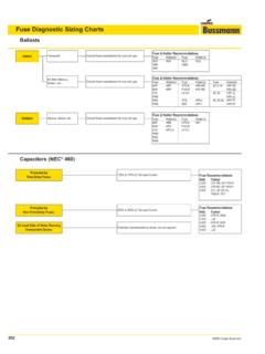
2 Cut an opening in the side of the Slip the heater into the duct until the hole is completely covered by fl anges around the Fasten the heater to the duct with sheet metal screws and seal openings with a suitable sealing If the heater is heavy, use additional hangers to support the FC or FT (Flanged type) (Please see drawings page 4). Flange both ends of the duct outwards on three sides to match the heater s fl Fasten the heater to the duct with sheet metal screws. (For heavy heaters, use nuts and bolts and additional hangers to support the heater). Seal openings with a suitable sealing Spacing Requirements to obtain Optimal air distribution over the heating elements of duct heaters are: (Please see drawings page 4). Note: Distances may vary for heaters installed in air handling units (AHU). 24 inches between the heater and fi lter frames. ** inches between the heater and elbows in the duct. ** inches between the heater and branches in the duct.
3 ** inches between the heater and sharp transitions of the duct. ** = minimum distance = the largest of two dimensions (W or H) up to 48 . Examples: heater of 12 x 12 minimum distance 12 . heater of 30 x 12 minimum distance 30 . Heater of 60 x 30 minimum distance 48 . 48 inches between the heater and a double outlet fan, except with split duct design. 30 inches between the heater and access doors or diffusers, except if a metal screen is supplied with the heater. 1 inch between the duct at the outlet side and combustible materials for a length of 72 , for vertical ducts only. For the fl anged type, 24 inches between the control box cover and obstructions to allow space for installation and service. For the slip-in type, width of the duct (dimension W) + depth of the control box + ten (10) inches between the control box cover and obstructions to allow slipping the heater out the duct and to allow safe Important Notes Do not install a duct heater in a vertical duct directly above a ceiling diffuser or an opening in the ceiling.
4 Do not install standard heaters outdoors. Order a heater with weatherproof control box instead. Do not install spray humidifi ers upstream of duct. Install it downstream instead. Do not cover the control box with thermal insulating materials. Use special air intake louvers of weatherproof construction for preheat duct heaters to avoid intake of water or snow particles Make sure that motorized damper blades are not blocked with snow or dirt. Inspect the dampers regularly to ensure a suitable airfl - Electrical Installation of THERMOLEC Disconnect all power sources before opening the control box and working Read the nameplate carefully and consult wiring diagram before starting to Supply wires: Use only wires suitable for 75 C. Wires shall be sized according to the Canadian Electrical Code requirements. All wires must be brought in through Disconnecting means: IInstall a disconnect switch close to the heater according to the code unless a disconnect switch is already built into the Control circuit wiring: Use class 2 wiring for control circuit connections to the duct Magnetic contactors: If magnetic contactors are mounted outside of the duct heater, use only contactors approved for: 250,000 operations when controlled by auto-reset thermal cut-out (A) and by other switching devices in series with this cut- out (thermostat, step controller, air fl ow switch, etc.)
5 100,000 operations when controlled by auto-reset thermal cut-out (A) alone. 100,000 operations when controlled by auto-reset thermal cut-out (A) plus manual reset cut-out in series.(A&M). 6,000 operations when controlled by manual reset cut-out (M) External Controls ratings: Rating of external control devices shall be suitable for handling the VA ratings as marked on the nameplate, otherwise, a back-up relay must be Air Flow Interlock: Heaters are generally supplied with two extra terminals marked I C for fan interlock or air sensing device connection. Remove jumper between terminals I and C before connecting the fan interlock, Select a suitable air fl ow sensing device of the differential pressure sensing type, with snap acting contacts. A slow make, slow brake device may cause undue cycling and in some instances chattering of the contactors. When fresh air dampers are used, make sure the heater is properly interlocked to prevent it from being energized before the damper is fully Operating THERMOLEC Minimum air fl ow.
6 Air fl ow below the value indicated on the nameplate could cause overheating and lead to the opening of the auto-reset thermal cut-out and/or manual reset cut-out. Any air fl ow switch should only be used to sense airfl ow or a pressure differential and not as a primary control to start or stop the duct heater. Warning. The air fl owing through the duct where the heater is installed shall not contain any combustible particles, nor any fl ammable vapor or Air Temperature. The air temperature of our standard duct heater should not exceed 27 C (81 F) at the heater inlet and 66 C (151 F) at the Minimum static pressure and air direction. The heater is protected by a pressure differential switch. To keep the contact of this switch closed, it is necessary to maintain a minimum total pressure of 0,07 inches of water for a constant fl ow. For proper installation follow the instructions on the label located on the control panel of the THERMOLEC duct Manual-reset thermal cut-out This protection device is standard on all heaters Please check the auto-reset thermal cut-out BEFORE starting the heater.
7 If any defect has been detected in the auto-reset thermal cut-out, it will be necessary to replace it before re-setting the manual- reset thermal Maintenance. All THERMOLEC heaters have been designed to operate long term without problems. Those responsible for equipment and maintenance should be aware of the Visual Inspection. THERMOLEC strongly recommends a periodic inspection. This precautionary step will help to keep your installation operating well. Note these eventual fi rst signs of problems: Accumulation of dust on the heating elements, signs of overheating on the heater frame, traces of water or rust on the control box. Electrical Inspection. Two weeks after startup , all electric connections to contactors should be checked and tightened. Prior to each heating season, check the resistance between the heating elements and ground. It is also recommended to check the electrical connections to heating elements, magnetic contactors, and main power lugs.
8 This inspection is recommended monthly during the fi rst four months of operation. After that, two inspections per heating season are suffi What are the checkpoints? - Check all fuses - Check the resistance to ground for each circuit - Check the resistance phase to phase for each circuit - Check the tightening of connections at all contactors and heating elements - Check all Off-season maintenance Where tubular heating elements are used, THERMOLEC strongly recommends that you start the heating system from time to time. This precaution will prevent moisture from infi ltrating through the terminal gaskets into the heating element and accumulating in the insulating powder. Should a heater be shut off for a long period, we recommend that you carefully check the resistance to ground for each circuit. It is important not to power a heater when too low a resistance to ground has been measured.
9 Control components such as step controllers or modulating valves (SCR) should be maintained and checked according to respective manufacturers instructions. Any defective components should be replaced only with approved original parts. Limited Warranty1 - THERMOLEC LTD guarantees it s heater resistance elements against any defect in workmanship and material for a period of two years and other built-in components for a period of one year, starting from the date of shipment from it s factory. This warranty is limited to equipment and components supplied by THERMOLEC LTD. 2 - Improper installation, misuse of this product, or repairs made by others without THERMOLEC LTD s authorization, will void this warranty. 3 - THERMOLEC LTD will repair or replace without charge, in its factory or in the fi eld at its own discretion, the heater or part, which upon manufacturer examination, is considered to be defective. 4 - THERMOLEC LTD shall not be held responsible for damage or delay and shall not be held liable for any charges resulting from the removal or replacement of the allegedly defective heater.
10 5 - THERMOLEC LTD shall not be held responsible for any incidental or consequential damage or delay due to workmanship or material. No additional charge will be accepted for repair, re-placement or modifi cation if prior written authorization was not obtained from THERMOLEC LTD6 - Any control device or accessory, supplied with the heater, to be mounted or connected re-motely, will only be guaranteed by the manufacturer per conditions stated in paragraph - Components supplied for repairs are guaranteed for the balance of the original warranty or 90 days, whichever is - All repairs made at THERMOLEC LTD s factory after the warranty period, is guaranteed for 30 days from the date of the FrameHeater too close to fanHeater too close to filterHeater too close to elbowHeater too close to transitionOverheatingConditionsHEATERM inimum recommended distancefor safety and serviceDim. "W"Dimension "W" + 10"ObstructionType SC or ST24"Type FC or FTAirDirectionInstallation of the FLANGED typeFC or FTInstallation of the SLIP-IN typeSC or STHeaterHeaterDuctDuctHeater too close to a fanHeater too close to a filterFilter frameHeater too close to an elbowAvoid these overheating conditionsHeater too close to a transitionMinimum recommended distancefor safety and serviceObstructionObstruction24 Type FC or FTType SC or STDimension W + 10 Dim.