Transcription of T Railway Technology Today 8 (Edited by Kanji …
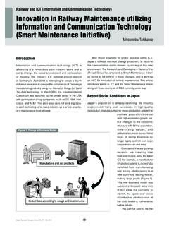
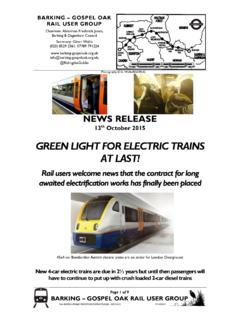
1 Technology Technology Railway Technology Today 8 ( edited by Kanji Wako). Signalling Systems for Safe Railway Transport Tetsuo Takashige applied is longer for trains than it is for blocks and to control the signals for each Introduction road vehicles. Consequently, only one block. All double-tracked sections in Japan train can occupy a specific section of track use the automatic block system. As Trains could not run safely without at one time. Such a section of track is Figure 2a shows, there are basically three signalling devices. This article looks at called a block. Track circuits are used to signal aspects: red, meaning stop four tools that ensure Railway safety in determine whether a train is in a specific immediately before entering the next Japan: block systems, train control systems, block. track section occupied by an ahead train;. train traffic control systems, and wireless Figure 1 shows how the rails form part of yellow, meaning proceed with caution at communications devices.
2 An electric circuit (track circuit). When a speed no greater than 45 km/h (55 km/h the train's wheels pass a certain point, they or faster is permitted on some sections) as cause a short circuit, preventing electric far as the signal, and green, meaning the Block Systems current from proceeding further. This next track section is clear and the train makes it possible to detect a train in a can enter that section at the maximum Automatic block system block. speed. In heavily used sections, two other Braking distance the distance needed to An automatic block system uses the track signal aspects are also used (Fig. 2b): two come to a complete halt after brakes are circuit to automatically detect trains in yellow lights (restricted speed), and one yellow and one green light (reduced speed). Figure 1 General Principles of Track Circuit Other block systems Train wheels short-circuit passage of current to receiver In addition to the automatic block system, a number of other block systems are used on single tracks.
3 In many cases, a track circuit system or an electronic block system (electronic coding verification Train system) is used. Both are semi-automatic block systems. Transmitter Receiver Activated relay released The track circuit system controls train by train short-circuiting rails movement in the blocks between stations, and involves interlocking signal levers at Figure 2 Automatic Block Signalling System (a) Normal track section STOP CAUTION CLEAR R : Red Y : Yellow G Y R G Y R G Y R G : Green T : Transmitter (power supply). R: Receiver (track relay). R T R T R T R T. Signal current cut (b) High-density traffic track section STOP RESTRICTED SPEED CAUTION REDUCED SPEED CLEAR. Y Y R Y G Y Y R Y G Y Y R Y G Y Y R Y G Y Y R Y G. R T R T R T R T R T R T. 44 Japan Railway & Transport Review 21 September 1999 Copyright 1999 EJRCF. All rights reserved. Reproduction in whole or in part without permission is prohibited. Figure 3 Operation of ATS-S System Alarm Emergency brakes automatically applied rings to stop train if driver fails to brake within 5 seconds 5-second interval Train speed Pattern followed when driver brakes to stop STOP signal Ahead train Alarm rings here Alarm distance (emergency braking distance + safety margin).
4 STOP signal White light ON. STOP signal Red light ON, bell rings Alarm rings When driver brakes STOP signal within 5 seconds to stop White light ON, chime rings White light ON, chime rings Train stops 5-second interval STOP signal Emergency If driver does not brake brakes applied within 5 seconds to stop Red light ON, bell rings Red light ON, bell rings the two stations that a train is travelling with serious loss of life in the early 1960s stops at the ground coil, the train can still between. The train's departure and arrival resulted in the installation of the so-called proceed under his control through a stop are detected by the track circuits at the Automatic Train Stop (ATS) system signal. So-called 'absolute stop' ground station entrance and exit. throughout Japan. In the ATS system, an coils that do not depend on driver In the electronic block system, each train alarm sounds in the cab when the train ackowledgement are installed in stations has a radio communications device that approaches a stop signal, warning the and at start signals to prevent any possibility transmits the train's ID.
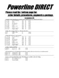
5 When the driver is driver to stop. If he fails to apply the brakes, of an accident occurring due to the driver ready to leave a station, he presses a the ATS stops the train automatically. moving ahead by mistake. button and the signal changes automatically (Figure 3 shows the operation of the ATS-S A new ATS-P type of system that does not to green. When the train arrives at the system used by the JRs.) depend on driver acknowledgement has next station, the train's ID is transmitted The ATS system uses ground coils been installed recently, mostly in the to a receiver, clearing the block. This type installed on the track some distance before Tokyo and Osaka regions. Ground coils of electronic block system requires fewer signals. If a train passes a coil when the communicate between the ground and staff because the driver basically controls signal aspect is stop, an alarm is sent the trains (Fig. 4) and train braking patterns the block.
6 Immediately to the driver, regardless of are monitored by the ground coils to the train speed. If the driver does not ensure that the trains stop before a stop stop within 5 seconds after the alarm is signal. If a train exceeds the speed Train Control Systems received, the emergency brakes are applied permitted by the braking pattern, the automatically to stop the train. In other service brakes are applied automatically Automatic Train Stop (ATS) words, the emergency brakes are not to stop the train. The train can then The driver must always obey the signal, applied if the driver applies the brakes proceed again, but only in accordance but the possibility of human error can and presses the Acknowledge button. with instructions received from the next cause serious accidents. Two rail accidents However, this means that if the driver coil. This system offers higher safety Copyright 1999 EJRCF. All rights reserved. Reproduction in whole or in part without permission is prohibited.
7 Japan Railway & Transport Review 21 September 1999 45. Technology levels, because it does not depend on Automatic Train Control (ATC) Automatic Train Operation (ATO) system driver acknowledgement. The Automatic Train Control (ATC) system can automatically control departure from Private railways in Japan have installed was developed for high-speed trains like stations, the speed between stations, and an improved version of the ATS-S system the shinkansen, which travel so fast that the the stop position in stations. It has been throughout most of their networks. This driver has almost no time to acknowledge installed in some subways. system offers on-board speed verification trackside signals. The ATC system sends capability and, since it can apply train AF signals carrying information about the Digital ATC. brakes automatically, does not depend on speed limit for the specific track section The ATC system has been used to control driver acknowledgement.
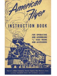
8 Along the track circuit (Fig. 5). When all sections of shinkansen tracks ever since In an intermittent control system using these signals are received on board, the the first shinkansen in 1964 and there has coils, no information is received before train's current speed is compared with the never been a collision. However, ATC has the train passes the coil, meaning that speed limit and the brakes are applied three disadvantages. First, the headway signal changes in heavily used sections automatically if the train is travelling too cannot be reduced due to the idle running do not provide a suitable level of fast. The brakes are released as soon as time between releasing the brakes at one compliance. To alleviate this problem, the train slows below the speed limit. speed limit and applying the brakes at the the railways have installed a continuous This system offers a higher degree of next slower speed limit. Second, the control ATS system for some track sections.
9 Safety, preventing collisions that might be brakes are applied when the train achieves This system uses an audio-frequency (AF) caused by driver error, so it has also been maximum speed, meaning reduced ride current to transmit ATS-related information installed in heavily used lines, such as comfort. Third, if the operator wants to along the track circuit, making it possible Tokyo's Yamanote Line and some subway run faster trains on the line, all the related to receive information on board the train lines. relevant wayside and on-board equipment at any time. This system offers similar Although the ATC applies the brakes must be changed first. advantages to the ATC system described automatically when the train speed The digital ATC system uses the track circuits below. exceeds the speed limit, it cannot control to detect the presence of a train in the the motor power or train stop position section and then transmits digital data when pulling into stations.
10 However, the from wayside equipment to the train on Figure 4 Operation of ATS-P System Braking pattern created Transceiver Brake Recorder command Braking pattern Receive Speed logic check Brake unit unit Controller mechanism On-board transponder Signal aspect and distance TG to stop signal Electrical signal Ground coils Ground coils Ground coils Passive ground coils at 650 m at 180 m at 30 m (two in unit). No. 3 No. 2 No. 1 Signal aspect data Repeater Repeater Repeater Data circuit (1 pair) Code To central monitoring equipment processor (system supervision). Power supply circuit (1 pair). TG: Tachometer generator 46 Japan Railway & Transport Review 21 September 1999 Copyright 1999 EJRCF. All rights reserved. Reproduction in whole or in part without permission is prohibited. Figure 5 ATC Train Running Pattern Figure 6 Digital ATC Train Running Pattern Light braking force at first 300 300. Full service braking 275 275. Alarm Running pattern 230 230.