Transcription of T TM ENGINEERING - Full Service Stocking Distributor for ...
1 TMTLIQUIFLO CHEMICAL PROCESSING PUMPStel. 908. 518. 0777fax. 908. 518. CHEMICAL PROCESSING PUMPSENGINEERINGGEAR PUMP BASICS External Gear Pump Principle of Operation & Advantages88-89 LIQUIFLO GEAR PUMPSM aximum Torque for Various Gear Combinations90 Theoretical Displacements90 Metal vs. Metal Gears90 Pumping Hot Liquids91 Pumping Viscous Liquids 91 Pumping Thin Liquids91 Magnetic Couplings92 Pumping Hot Liquids with Mag-Drive Pumps92 Temperature Control Jacket 92 Dual-Kan 92 Magnetic Drives93 OPTIONSPump-Motor Coupling & Mounting Options94 Relief Valves95 SEALINGMETHODSSeal Arrangements for Gear Pumps96-97 Mechanical Seal Configurations98 Unbalanced.
2 Semi-Balanced & Balanced Seals99 Seal Arrangements for Centrifugal Pumps100 METERINGM etering with Gear Pumps101 CHEMICAL DATAC hemical Classifications102-103 Chemical Resistance Chart104-107 FLUID DYNAMICSN ewtonian & Non-Newtonian Materials108-109 Viscosity vs. Temperature for Specific Chemicals110-111 Friction Loss Modulus Introduction112 Friction Loss Modulus Graphs for Steel Pipes113-120 Resistance of Valves & Fittings to Flow of Fluids121 MECHANICAL DATAF astener Torque Specifications122 Dimensional Data for Welded & Seamless Pipe123 MOTORSE lectrical Standards & Motor Enclosure Types124 NEMA Charts Hazardous & Non-Hazardous Classifications125 Torque, Speed, Power & Efficiency126 Torque vs.
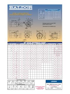
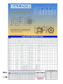
3 Speed Curves & Air Motors127 NEMA Motors quick reference Chart128 IEC Motors quick reference Chart129 APPLICATIONSGear Pump & Motor Selection Example130-131 Materials of Construction for Liquiflo Gear Pumps132-135 Material Selection Guidelines for Bearings & Shafts136-137 Centrifugal Pump Selection for Viscous Service138-141 Calculation of System NPSHA142 Application Data Sheet ( )143 FORMULASE ngineering Formulas144-145 CONVERSIONSV iscosity Units Conversion Table146-147 Physics Units Conversion Table148 Flow & Pressure Units Conversion Charts149 SYMBOLSG reek Alphabet150 Power-of-Ten Prefixes150 NOTESNote Pages151-152 This section of the catalog contains valuable information about gear and centrifugalpumps, and their application to pumping fluids for the chemical processing industry.
4 Please contact Liquiflo s ENGINEERING Department if you have any questions about thematerial in this catalog, or to assist you with your chemical pumping of ContentsIntroductionTMT87 TMT88tel. 908. 518. GEAR PUMP PRINCIPLE OF OPERATION & ADVANTAGESENGINEERING - Gear Pump BasicsThe external gear pump is a positivedisplacement (PD) type of pumpgenerally used for the transfer andmetering of liquids. The pump is sonamed because it has two gears thatare side-by-side or externalto eachother. (This nomenclature differen-tiates it from an internalgear pump,which has one gear positioned insidethe other.)
5 The gear pump is aprecision machine with extremelytight fits and tolerances, and iscapable of working against highdifferential pressures. The working principle of the externalgear pump is illustrated in Figure drive gear (that is driven by amotor) rotates an idler gear in theopposite direction. When the gearsrotate, the liquid, which is trapped inthe gear teeth spaces between thehousing bore and the outside of thegears, is transferred from the inlet sideofthe pump to the outlet side. It isimportant to note that the pumpedliquid moves around the gears andnot between the gears.
6 The rotatinggears continue to deliver a freshsupply of liquid from the suction (inlet)side of the pump to the discharge(outlet) side of the pump, withvirtually no pulsations. The meshing INLETDIRECTION OF FLOWOUTLETINLETOUTLETDRIVEGEARIDLERGEARH OUSINGC lockwise Rotationof Drive GearCounter-Clockwise Rotationof Drive GearIDLERSHAFTDRIVESHAFTof the gears on the discharge side of thepump forces the liquid out of the pumpand into the discharge piping. Figure 1also shows that the direction of rotation of the drive gear determinesthe direction of flow thru the pump, andwhich side of the pump is the inlet andwhich side is the outlet.
7 If the directionof rotation of the motor (and thereforethe drive gear) is reversed, the directionof flow thru the pump will also bi-directional flow characteristicisone of the many advantages inherentto gear important advantage of thegear pump is its self-priming pumps are capable of self-primingbecause the rotating gears evacuate air in the suction line. This produces apartial vacuum that allows the atmos-pheric pressure to force the liquid intothe inlet side of the pump. This ability ofthe gear pump makes it an ideal choicewhen the application requires that thepump be located above the liquid level,and the liquid must be lifted to thepump.
8 Because a gear pump cannotcreate a perfect vacuum, the total lift(including pipe friction losses) should notexceed about PSI, or about one-halfof the atmospheric tight clearances of the working partsinside a gear pump are what enable it to effectively pump liquids against highpressure. Low viscosity fluids such asalcohols and other solvents have moreof a tendency to slip thru these tightspaces from the higher-pressuredischarge side of the pump back to thelower-pressure suction side of the phenomenon of slipcauses a reduction in flow rate and pumpefficiency.
9 Slip depends on themagnitude of the differential pressure( , the difference between thedischarge and suction pressures), theviscosity of the liquid pumped and theworking clearances inside the particularpump that is used. Slip increases withdecreasing viscosity, increasingdifferential pressure and increasing gear-housing clearances, and is usuallymeasured as a percent decrease fromideal flow ( , flow with zero slip). Forfluid viscosities greater than about 50-100cP (depending on the particular pump),the slip is minor, but it still depends on thedifferential pressure.
10 This behavior isshown in Figure 2, which compares atypical gear pump s performance curvefor a thin fluid (such as water with aviscosity of about 1 cP at room temper-ature) with that of a moderately viscousfluid (such as a particular oil with aviscosity of 100 cP).Figure 1: Cross-sectional views of external gear pump demonstrating operating 908. 518. 0777fax. 908. 518. GEAR PUMP PRINCIPLE OF OPERATION & ADVANTAGES (continued) ENGINEERING - Gear Pump BasicsThe Flow vs. Pressure curves for the thinfluid have high slopes, which indicatesignificant reductions in flow rate withincreasing differential pressure ( , highslip).