Transcription of Table of Contents - Belden
1 Table of Contents technical Information Page No. Conductors technical Information Table 1: Solid Copper Wire, American Wire Gage Table 2: Stranded Copper Wire, American Wire Gage Table 3: Current Ratings for Belden Electronic Cables Table 4: Metric/Imperial/Circular Mills/AWG Equivalents Insulations and Jackets Insulations: Overview Jackets: Overview Characteristics of Popular Insulation and Jacket Compounds Table 4: Comparative Properties of Plastic Compounds Table 5: Comparative Properties of Fluoropolymers Table 6: Comparative Properties of Rubber Insulations Table 7: Nominal Temperature Ranges Shielding and Armoring Shielding: Overview Characteristics of Belden Shield Types 22.
2 Foil Shields Braid Shields Spiral/Serve Shields French Braid Shields Combination Shields Shield Types: Application Guide Table 8: Relative Cost Comparison of Shield Types Table 9: Shield Performance Comparison Armoring: Overview Metric Conversions Table 10: Temperature Conversions Table 11: Distance and Weight Conversion Formulas Table 12: Conductor Size Equivalents Belden Color Code Charts Cable Standards Reference Guide National Electrical Code (NEC) Impact of NEC Intended Uses of Appliance Wiring Materials (AWM) C(UL) Certifications FT1 Vertical Flame Test FT4 Vertical Flame Test Cables in Trays FT6 Horizontal Flame and Smoke Test NEC Cable Substitution Chart Canadian Electrical Code (CEC)
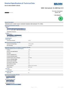
3 Substitution Chart Terms of Use of Master Catalog Environmental Regulations and Compliance Cable Packaging UnReel Reel-in-a-Box Glossary The information, graphs, tables and illustrations presented in this section are provided to assist Belden customers with the selection of the most appropriate cable for their application. For further assistance, contact Belden technical Support at: 1-800- Belden -1. T E C H N I C A L I N F O R M A T I O N Conductors Table 1: Solid Copper Wire, American Wire Gage Nominal OD Nominal Gage Nominal Nominal Weight Resistance @ 68 F.
4 (AWG) Circular MIL Area (Lbs. per 1000 Ft.). Inches mm ( /1000 Ft.). 10 .1019 .9989. 11 .0907 12 .0808 13 .0720 14 .0641 15 .0571 16 .0508 17 .0453 18 .0403 19 .0359 .912 20 .0320 .813 21 .0285 .724 22 .0253 .643 23 .0226 .574 24 .0201 .511 25 .0179 .455 .9699 26 .0159 .404 .7692 27 .0142 .361 .6100 28 .0126 .320 .4837 29 .0113 .287 .3836 30 .0100 .254 .3042 31 .0089 .226 .2413 32 .0080 .203 .1913 33 .0071 .180 .1517 34 .0063 .160 .1203 35 .0056 .142 .09542 36 .0050 .127 .07568 37 .0045 .114 .0613 38 .0040 .102 .04759 39.
5 0035 .089 .03774 40 .0031 .079 .02993 Information from National Bureau of Standards Copper Wire Tables Handbook 100. Unparalleled Performance Belden is one of only a very few cable manufacturers to draw and anneal its own conductors. This is a time-consuming process, but it allows us to ensure signal integrity, as well as proper physical characteristics. In addition, the standards under which we design and manufacture our fiber optic cabling are among the strictest in the industry. The result is a comprehensive offering of products which give unparalleled performance and can satisfy your most demanding operating and environmental challenges.
6 F o r m o r e i n f o r m a t i o n , c o n t a c t B e l d e n Te c h n i c a l S u p p o r t : 1 - 8 0 0 - B E L D E N - 1 w w w . b e l d e n . c o m T E C H N I C A L I N F O R M A T I O N Conductors Table 2: Stranded Copper Wire, American Wire Gage Approximate OD Max. Resistance*. Gage Stranding Min. Average ASTM Min. Min. Weight @ 68 F. (AWG) (Nom. AWG) OD of Strand Circular MIL Area ( Ft.). Inches mm ( /1000 Ft.). 36 7x44 .0019 .006 .152 25 .076 34 7x42 .0024 .0075 .191 .121 32 7x40 .0030 .0093 .236 64 .195 32 19x44.
7 0018 .010 .254 64 .195 30 7x38 .0038 .012 .305 100 .304 30 19x42 .0023 .012 .305 100 .304 28 7x36 .0048 .015 .381 159 .484 28 19x40 .0029 .016 .406 159 .484 27 7x35 .0054 .017 .432 202 .614 26 7x34 .0060 .019 .483 253 .770 26 10x36 .0050 .021 .533 253 .770 26 19x38 .0036 .020 .508 253 .770 24 7x32 .0076 .024 .610 404 24 10x34 .0064 .024 .610 404 24 19x36 .0046 .024 .610 404 24 42x40 .0031 .023 .584 404 22 7x30 .0096 .030 .762 640 22 19x34 .0058 .031 .787 640 22 26x36 .0050 .030 .762 640 20 7x28 .0126 .038 .965 1020 20 10x30.
8 0101 .037 .940 1020 20 19x32 .0073 .037 .940 1020 22 technical Information 20 26x34 .0063 .036 .914 1020 20 42x36 .0049 .038 .965 1020 18 7x26 .0152 .048 1620 18 16x30 .0101 .047 1620 18 19x30 .0092 .049 1620 18 42x34 .0062 .047 1620 18 65x36 .0050 .047 1620 16 7x24 .0192 .060 2580 16 19x29 .0117 .058 2580 16 26x30 .0100 .059 2580 16 65x34 .0063 .059 2580 16 105x36 .0050 .059 2580 14 7x22 .0242 .076 4110 14 19x26 .0147 .071 4110 14 42x30 .0099 .075 4110 14 105x34 .0063 .075 4110 12 7x20 .0305 .096 6530 12 19x25 .0185 .093 6530 12 65x30.
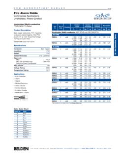
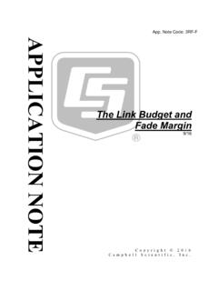
9 0100 .095 6530 12 165x34 .0063 .095 6530 10 37x26 .0167 .115 10380 10 65x28 .0126 .120 10380 10 105x30 .0099 .118 10380 *AWG 10 through 30 per UL Subject 13. Belden has standardized on the stranded conductors used in the design of all Belden products. These preferred constructions, based on standard industry practices, are marked with a symbol. F o r m o r e i n f o r m a t i o n , c o n t a c t B e l d e n Te c h n i c a l S u p p o r t : 1 - 8 0 0 - B E L D E N - 1 w w w . b e l d e n . c o m T E C H N I C A L I N F O R M A T I O N Conductors Table 3: Current Ratings for Belden Electronic Cables The maximum continuous current rating for 100.
10 90. an electronic cable is limited by conductor 80. size, number of conductors contained 70. within the cable, maximum temperature 60. rating of the cable, and environmental 50. conditions such as ambient temperature 40. and air flow. To use the current capacity 30. chart, first determine conductor size, temperature rating, and number of Current (in Amperes). 20. conductors from the applicable product description for the cable of interest. 10 35 C Temp. Rise Next, find the current value on the chart 9 Above Ambient for the proper temperature rating and 8.