Transcription of TABLE OF CONTENTS – CONCRETE DECK SLAB …
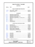
1 CONCRETE deck slab TABLE OF CONTENTS - chapter 10 VOL. V - PART 2 DATE: 10 Mar2015 SHEET 1 of 2 FILE NO. TABLE OF CONTENTS CONCRETE deck slab chapter 10 FILE NO. TITLE DATE TABLE OF CONTENTS AND INTRODUCTION TABLE of CONTENTS - chapter 10 .. 10 Mar2015 TABLE of CONTENTS - chapter 10 .. 01 Jul2011 Introduction - chapter 10 .. 10 Mar2015 deck slab DESIGN LRFD General .. 10 Mar2015 Part Transverse Sections .. 10 Mar2015 Part Transverse Sections .. 10 Mar2015 deck slab Design TABLE .. 10 Mar2015 Cantilever Design .. 10 Mar2015 Cantilever Design .. 10 Mar2015 Sample Design Calculations .. 10 Mar2015 Sample Design Calculations .. 10 Mar2015 Sample Design Calculations .. 10 Mar2015 Sample Design Calculations .. 10 Mar2015 Sample Design Calculations.
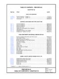
2 10 Mar2015 Sample Design Calculations .. 10 Mar2015 Maximum Live Load Moment TABLE .. 10 Mar2015 deck slab DETAILS CONCRETE Bolster (Haunch) Detail .. 14 Dec2012 Continuous deck slab Retrofitting Existing Bridge Detail .. 16 Jan2014 deck slab CONCRETE PLACEMENT CONCRETE Placement Schedule - Steel .. 16 Jan2014 CONCRETE Placement Schedule Prestressed .. 16 Jan2014 deck slab ELEVATIONS deck slab Elevation Layout Notes .. 17 Dec2008 Sample Computations .. 17 Dec2008 * Indicates 11 x 17 sheet; all others are 8 x 11. VOL. V - PART 2 DATE: 01 Jul2011 SHEET 2 of 2 CONCRETE deck slab TABLE OF CONTENTS - chapter 10 FILE NO. TABLE OF CONTENTS CONCRETE deck slab chapter 10 FILE NO. TITLE DATE SAMPLE PLAN SHEETS General * Sample Plan Sheet deck Plan - Skew angle 0 to 20.
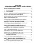
3 17 Dec2008 * Sample Plan Sheet deck Plan - Skew angle over 20 .. 17 Dec2008 * Sample Plan Sheet deck Plan - Curved Check List deck 17 Dec2008 * Indicates 11 x 17 sheet; all others are 8 x 11. CONCRETE deck slab INTRODUCTION - chapter 10 VOL. V - PART 2 DATE: 10 Mar2015 SHEET 1 of 1 FILE NO. INTRODUCTION It is the intent of this chapter to establish the practices and specific requirements of the Structure and Bridge Division for the design and detailing of CONCRETE deck slabs. It will also provide design aids and other sources of information along with cross references to other parts of this manual to assist in the design and preparation of plans. References to LRFD Design Specifications refer to the current AASHTO LRFD Bridge Design Specifications, Interims, and VDOT Modifications (current IIM-S&B-80).
4 References to standard specifications in this chapter refer to the AASHTO Standard Specifications for Highway Bridges, 1996 including the 1997 and 1998 Interims and VDOT Modifications. The practices and requirements set forth herein are intended to supplement or clarify the requirements of the AASHTO specifications and to provide additional information to assist the designer. In the event of conflict(s) between the practices and requirements set forth herein and those contained in the AASHTO specifications, the more stringent requirements shall govern. It is expected that the users of this chapter will adhere to the practices and requirements stated herein. Several major changes and/or additions to the past office practice (Part 2) are as follows: 1. Changed deck slab reinforcing steel dimensioning from centerline of bars to clearance of bars.
5 Changed top layer from 2 to center of bar to 2 clear and bottom layer from 1 to center of bar to 1 clear to coincide with VDOT Road and Bridge Specifications. 2. Revised cantilever design requirements. NOTE: Due to various restrictions on placing files in this manual onto the Internet, portions of the drawings shown do not necessarily reflect the correct line weights, line types, fonts, arrowheads, etc. Wherever discrepancies occur, the written text shall take precedence over any of the drawn views. CONCRETE deck slab deck slab DESIGN LRFD GENERAL VOL. V - PART 2 DATE: 10 Mar2015 SHEET 1 of 13 FILE NO. General: A. CONCRETE deck slabs on bridges designed in accordance with AASHTO LRFD for HL-93 loading. Design shall be in accordance with LRFD Sections 3, 4, 5, 9, 13, and VDOT Modifications.
6 The empirical design method shall not be used. Main reinforcement may be designed by use of the tables on File No. This TABLE is based on the requirements of LRFD Design Specifications and a ratio of A s/As = A set of example calculations is provided for a slab design and cantilever design in File Nos. thru Distribution steel is to be designed in accordance with LRFD Article and office modifications. A set of example calculations is provided in File Nos. thru B. Unless circumstances require other thicknesses, the following shall be used for deck slabs supported by stringers, according to the c-c stringer spacings shown: Minimum slab Thickness Spacing of Stringers Steel CONCRETE 7 1/2 6 -0 or less 6 -9 or less 8 over 6 -0 to 7 -0 over 6 -9 to 7 -9 8 1/2 over 7 -0 to 10 -0 over 7 -9 to 10 -0 9 over 10 -0 to 12 -0 over 10 -0 to 12 -0 C.
7 Main reinforcing bars shall be detailed as follows for the usual simple spans (long spans, non-parallel beams/girders, etc. may require deviation from this) LRFD Article : 1. For skew angles from 0 to 20 , main reinforcement shall be placed parallel to ends of slab (s) with truss-type slab bars alternating with straight bars top and bottom. 2. For skews over 20 , all main reinforcement shall be placed perpendicular to centerline of bridge. Main reinforcement in the end sections shall be detailed as straight bars top and bottom. Section of slab requiring full-length main bars shall be detailed with truss-type bars alternating with straight bars top and bottom. Consideration should be given to reinforcing the ends of the slab by placing additional slab bars in the vicinity of and parallel to end diaphragms. 3. Main reinforcement bars shall be #5, distribution bars shall be #4, and reinforcing bars in negative moment regions over piers shall typically not be greater than a #6 bar.
8 4. Longitudinal bars may be detailed using a series of 40 bars with one bar at the end to make up the remaining length. D. For deck slabs cast in a single pour wider than 60 to 80 , a longitudinal or construction joint should be considered. For deck slabs cast in a single pour wider then 80 , a longitudinal joint shall be provided. E. deck reinforcement shall typically be detailed as straight bars without hooks unless there is insufficient length for development (top bars only). CONCRETE deck slab deck slab DESIGN LRFD PART TRANSVERSE SECTIONS VOL. V - PART 2 DATE: 10 Mar2015 SHEET 2 of 13 FILE NO. CONCRETE deck slab deck slab DESIGN LRFD PART TRANSVERSE SECTIONS VOL. V - PART 2 DATE: 10 Mar2015 SHEET 3 of 13 FILE NO. CONCRETE deck slab deck slab DESIGN LRFD deck slab DESIGN TABLE VOL.
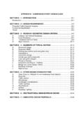
9 V - PART 2 DATE: 10 Mar2015 SHEET 4 of 13 FILE NO. deck DESIGN TABLE Span Length (S) (ft.) Reinforcement Steel Required Steel Beams/Girders Prestressed Conc. Beams deck Thickness (t) (in.) Area ( ) Bar Spacing deck Thickness (t) (in.) Area ( ) Bar Spacing 7 1/2" #5 @ 7 * 7 1/2" #5 @ 7 * #5 @ 7 * #5 @ 7 * #5 @ 7 * #5 @ 7 * #5 @ 7 * #5 @ 7 * #5 @ 7 * #5 @ 7 * #5 @ 7 * #5 @ 7 * #5 @ 7 * #5 @ 7 * #5 @ 7 * # 5 @ 7 * #5 @ 7 * #5 @ 7 * 8 #5 @ 7 1/2 * #5 @ 7 * #5 @ 7 1/2 * #5 @ 7 *
10 #5 @ 7 1/2 * #5 @ 7 * #5 @ 7 1/2 * 8 #5 @ 7 1/2 * 8 1/2" #5 @ 8 * #5 @ 7 1/2 * # 5@ 8 * #5 @ 7 1/2 * #5 @ 8 * #5 @ 7 1/2 * #5 @ 8 * 8 1/2" #5 @ 8 * #5 @ 8 * #5 @ 8 * #5 @ 8 * #5 @ 8 * #5 @ 7 1/2 #5 @ 8 * #5 @ 7 1/2 #5 @ 8 * #5 @ 7 1/2 #5 @ 8 * #5 @ 6 1/2 #5 @ 8 * #5 @ 6 1/2 #5 @ 7 1/2 #5 @ 6 #5 @ 7 1/2 9 #5 @ 6 1/2 9 #5 @ 8 #5 @ 6 #5 @ 7 1/2 # 5 @ 6 #5 @ 7 1/2 #5 @ 5 1/2 #5 @ 7 #5 @ 5 1/2 #5 @ 7 #5 @ 5 #5 @ 7 #5 @ 5 #5 @ 6 1/2 #5 @ 5 # 5 @ 6 1/2 Design assumptions: 1.