Transcription of TABLE OF CONTENTS - DAVCO Technology
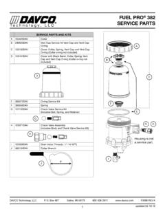
1 F1215 REV ETABLE OF CONTENTSA pplications, Models, and Options ..1 How it Works ..1 SEEING IS BELIEVING ..2 Dimensions and Specifications ..3 Important Safety Precautions ..4 Installation Instructions ..512 VDC And 24 VDC Electric Pre-heater Installation ..7 Water in Fuel Sensor (WIF) Installation ..8 Preventive Maintenance ..9 Filter Change Procedure ..10 Visual Diagnostics With Clear Cover ..11 Visual Diagnostics - Air vs . Vapor Bubbles ..12 Diagnostic Procedures - Air Leaks .. 13 Diagnostic Procedures - Heater Testing ..14 Check Valve Diagnostics ..15 Service Parts ..16 Warranty Policy ..17 Parts Return Policy ..18 FOR UPDATED INFORMATION, VISIT PRO 243 Technical ManualDIESEL PRO 243 TECHNICAL MANUALT echnology, LLC1 DAVCO Technology , LLC P. O. Box 487 Saline, MI 48176 800-328-2611 F1215 REV EThe Diesel Pro 243 combines the features of fuel filtration, fuel/water separation and fuel filter preheating into a single, compact unit intended for medium duty diesel engines used in highway, construction, mobile or stationary applications.
2 Applications Any diesel engine with fuel flow rates up to 60 gph Class 4, 5, & 6 Trucks Pickup Trucks Refrigeration Units Biodiesel Applications School bussesModels and Options Base Model - Unheated Electric heater (one heater port) 12 VDC 24 VDC 120 VAC Overnight heater Water-In-Fuel (WIF) sensorFUEL TANKENGINE LIFT PUMPINJECTIONPUMPFuel from fuel tankto Diesel ProFuel to fuel tank Fuel to engine from Diesel ProFuel System DiagramHOW IT WORKSAPPLICATIONS, MODELS, AND OPTIONS Fuel from the tank enters the Fuel Processor body (suction side of the fuel system) . Large contaminants and free water are separated from the fuel and remain in the body . Fuel rises into the clear cover . Contaminants and emulsified water are captured by the filter media . Fuel level rises to maintain a fuel path through the clean filter media with low restriction . Clean, water-free fuel exits the Fuel Processor and flows to the engine fuel injection system.
3 DIESEL PRO 243 TECHNICAL MANUALT echnology, LLC2 DAVCO Technology , LLC P. O. Box 487 Saline, MI 48176 800-328-2611 F1215 REV E See when NOT to change the fuel filter . See the condition of the fuel . Seeing what collects on the filter media or what s happening inside the clear cover can help diagnose many fuel and mechanical conditions . Filter on Top configuration . Water and debris removed from the fuel falls to the lower chamber and stays away from the filter media resulting in longer filter life . Built in protection when priming the fuel filter . Unfiltered fuel is kept on the dirty side of the filter media during priming ensuring only clean fuel reaches the engine . Patented media . The Best in Class StrataPore media removes 98% of free and emulsified water over the life of the filter . This far exceeds the performance of cellulose media . When new, the fuel level in the filter will be very low with minimal restriction.
4 As the filter is used, contami-nants collect on the filter from the bottom up . Fuel rises on the filter indicating remaining filter life .Fuel level at filter wrap level. Even though the fuel level is now more than half of the filter element, the fuel is still flowing through clean media at minimal restriction levels . The filter still has significant life remaining .Fuel level increases in clear cover. As contaminants collect on the filter, the fuel rises to a non-contaminated section of the filter, providing optimal filtration while main-taining lowest restriction .The filter element is now completely covered by fuel. At this point, all of the media s surface area is utilized . Restriction is increasing and the filter element should be changed at the next scheduled maintenance interval . SEEING IS BELIEVING DIESEL PRO 243 TECHNICAL MANUALT echnology, LLC3 DAVCO Technology , LLC P. O. Box 487 Saline, MI 48176 800-328-2611 F1215 REV EDIMENSIONS AND ( ) ( ) MAX.
5 41 ( ) 2 HOLES RECOMMENDED MINIMUM SERVICE ( ) ( ) ( ) ( ) ( ) ( ) LEFT SIDEBOTTOMRIGHT SIDEFRONTAll dimensions are in inches (millimeters)SpecificationsHeight Overall13 .00 in (330 .2 mm)Depth Overall5 .80 in (147 .3 mm)Width, max .6 .30 in (160 .0 mm)Mount Bracket Centers5 .25 in (133 .4 mm)Weight, dry5 .7lbs-5 .80 lbsFuel In Connection1/2"-14 NPTFFuel Out Connection1/2"-14 NPTFF ilter Service Clearance Min1 .50 in (38 mm)Max Fuel Flow60 gphElectric Pre-heater12 VDC, 150W, 13A120 VAC 75W, .65 AFiltration Performance at 60 GPHM icronCoarse Water Removal (%)Emulsified Water Removal (%)Dirt Holding Capacity (grams)7 mic99 .698 .9118 10 20 30 40 50 60 70 80 90 Restriction vs. FlowFlow (gph)Differential Pressure (in-Hg)DIESEL PRO 243 TECHNICAL MANUALT echnology, LLC4 DAVCO Technology , LLC P. O. Box 487 Saline, MI 48176 800-328-2611 F1215 REV E IMPORTANT SAFETY PRECAUTIONSG eneral Safety Precautions Read all instructions before use to avoid injury.
6 To avoid serious injury or death, follow the safety information in this document . Keep this manual . If you need to replace the manual, call customer service at 800-328-2611 or visit www . DAVCO .com/documents for a replacement . Read all product safety labels . Refer to appropriate regulations for environmental and workplace safety rules .WARNING: To prevent personal injury Scalding hazard: When diesel fuel is circulated through an operating engine, it can become very hot . Do not al-low fuel to come in contact with eyes or unprotected skin . Allow the engine and fuel to cool to ambient tempera-ture before replacing the fuel filter or performing service operations which could result in spillage of fuel from the fuel system . Fire Prevention: Heated fuel can form combustible vapor mixtures in the area around the fuel source . To elimi-nate the potential for fire, keep open flames, sparks or other potential ignition sources away from the work area.
7 Do not smoke during filter replacement or service operations . Inhalation Precaution: Always perform engine or vehicle fuel system maintenance in a well ventilated area that is kept free of bystanders . The ignition key must be in the off position, unless otherwise directed . To avoid unintentional engine startup, use a lockout key and/or signage to alert personnel that work is being performed .Government Regulations Engine fluids (oil, fuel, and coolant) may be a hazard to human health and the environment . Handle all fluids and other contaminated materials (such as filters and rags) in accordance with applicable regulations . Recycle or dis-pose of engine fluids, filters, and other contaminated materials according to applicable regulations .DIESEL PRO 243 TECHNICAL MANUALT echnology, LLC5 DAVCO Technology , LLC P. O. Box 487 Saline, MI 48176 800-328-2611 F1215 REV EInstallation LocationThe Diesel Pro must be installed between the fuel tank and the fuel transfer pump.
8 In some cases, the Diesel Pro can be used as the only fuel filter in the system . This is generally dependent on the engine model year . Consult the engine manufacturer for their recommendation . If the Diesel Pro can be used as a single filter, DAVCO offers a diverter cap to replace the secondary filter . (See Diverter Cap Installation section)Mounting the Diesel ProMount the Diesel Pro keeping the following points in mind: Do not install the Diesel Pro directly on the engine. Mount vertically with the cover and element pointing up . Make sure there is enough top and side clearance for the cover to be conveniently removed for filter replace-ment (3 .5" minimum) . The Diesel Pro MUST be installed so that the Filter Element is above the FULL level of the fuel tank . If mounted below full tank level, a shut off valve will be required at the inlet to allow filter changes without over-flow of fuel . 1 . With the engine shut down and at ambient temperature, close the fuel shutoff valve (if equipped) and place a suitable container under the fuel filters.
9 2 . Remove the primary fuel filter element assembly, sedi-menter, and/or water separator . Drain the used element and dispose of it in an environmentally responsible manner, according to state and/or federal (EPA) recom-mendations . The fuel can be returned to the tank .3 . Mount the Diesel Pro in the desired location using 3/8" Grade 8 hardware . Fuel Line RoutingTo minimize fuel system restriction, observe the follow-ing guidelines when plumbing the fuel system: Keep the fuel line routing as smooth as possible with no low-hanging loops which can trap water . Use 90 elbows only when necessary . If the fuel hoses are cut to length on the job, be sure that the inner liner of the fuel hose is not cut by the fit-ting, which can cause check valve performance issues . Make sure hoses are clean and free of debris before installing . To avoid damaging the aluminum Diesel Pro body, do not overtighten fuel lines or fuel line fittings.
10 1 . Route the fuel supply line from the pick up on the fuel tank to the Diesel Pro inlet (labeled Fuel In ) .2 . Route the fuel outlet line from the Diesel Pro outlet (labeled Fuel Out ) to the inlet of the fuel pump .Note: The inlet and outlet fittings can be moved from side to side depending on the applications needs . (Ex-ample : FUEL IN right and FUEL OUT right, See Figure 2) Be sure to use only ONE INLET and ONE OUTLET port per installation . From Fuel TankTo Lift PumpFigure 1 INSTALLATION INSTRUCTIONSDIESEL PRO 243 TECHNICAL MANUALT echnology, LLC6 DAVCO Technology , LLC P. O. Box 487 Saline, MI 48176 800-328-2611 F1215 REV EPriming the Fuel System1 . Check to make sure the drain valve at the base of the Diesel Pro is closed .2 . Remove the vent cap from the top of the clear cover . Fill the Diesel Pro full with clean fuel . Reinstall the vent cap . Tighten the vent cap by hand until it clicks.