Transcription of TABLE OF CONTENTS - MyAlarm.com
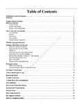
1 1 TABLE OF CONTENTSFEATURES2 Keypad Programmable .. 2 EEPROM Memory .. 2 Static/Lightning Protection .. 2 Supervision .. 2 Operation .. 2 SPECIFICATIONS2PC1550 Control Panel .. 2PC1500RK Keypad .. 2 INSTALLATION3 Mounting the Panel .. 3 Mounting the Keypad .. 3 Auxiliary Power Connection .. 3 PGM Terminal Connections .. 3 Bell/Siren Connection .. 3 Keypad Wiring .. 3 Fire Zone Wiring .. 3 Burglary Zone Wiring .. 3AC Power Wiring .. 3 Battery Connection .. 3 Telephone Line Wiring .. 3 GUIDELINES FOR LOCATING SMOKE DETECTORS4 KEYPAD FUNCTIONS5 Introduction .. 5 Master Code .. 52nd Master Code .. 5 Installer s Programming Code .. 5 Arming .. 5 Auto-Bypass/Home-Away Arming .. 5 Arming Without Entry Delay .. 5 Disarming .. 5 Zone Bypassing.
2 5 Trouble Conditions .. 5 Alarm Memory .. 6 Downloading Callup Command .. 6 User Programming Commands .. 6 EEPROM Reset .. 6 User Function Commands .. 6 Utility Output Command .. 7 Installer s Programming Command .. 7 Arming without Entry Delay .. 7 Arming For The Night .. 7 Quick-Exit Command .. 7 Quick-Arm Command .. 7 Keypad Zones .. 7 PROGRAMMING GUIDE8 Introduction .. 8 Programming .. 8 Program Data Review .. 8 Binary Data Display .. 8 HEX Data Programming .. 8 PROGRAMMING SECTIONS8[00] Binary Programming .. 8[01] 1st Phone Number .. 8[02] 1st Account Code .. 8[03] 2nd Phone Number .. 9[04] 2nd Account Code .. 9[05] to [10] Reporting Codes .. 9[05] Zone Alarm Reporting Codes .. 9[06] Zone Restoral Reporting Codes .. 9[07] Closing (Arming) Reporting Codes.
3 9 Partial Closing Reporting Code .. 9[08] Opening (Disarming) Reporting .. 9 Codes After Alarm Reporting Code .. 9[09] Priority Alarms and Restorals .. 9[10] Maintenance Alarms and Restorals .. 10[11] Zone Definitions .. 10[12] 1st System Option Code .. 11[13] 2nd System Option Code .. 11[14] 3rd System Option Code .. 11[15] Communication Variables .. 11[16] Zone Bypass Mask .. 11[17] System Times .. 11[18] Auxiliary Delay Loop .. 12 Entry/Exit Times .. 12[19] System Clock Times .. 12[20] New Installer s Code .. 12[21] New Master Code .. 12[22] 2nd Master Code .. 12[23] Communication Formats .. 12[24] Programmable Output Options .. 13 PGM Terminal .. 13[25] Communicator Call Directions .. 13[26] Downloading Telephone Number.
4 13[27] Downloading Access Code .. 13[28] Panel Identification Code .. 13[29] Number of Rings Before Answering .. 13[30] Reset to Factory Default .. 13[31] 4th System Option Code .. 13[32] 5th System Option Code .. 14[33] Answering Machine Double Call Timer .. 14[34] 6th System Option Code .. 14[35] LINKS1000 Test Reporting Code .. 14[36] Keypad Lockout Control .. 14[90] Installer s Lockout Enable .. 14[91] Installer s Lockout Disable .. 14 FOR THE RECORD15 PROGRAMMING WORK SHEETS16 NOTES FOR UL INSTALLATIONSThis equipment is UL listed in accordance with standard UL1023(Household Burglar - Alarm System Units), standard UL985(Household Fire Warning Units) and UL1635 (Digital AlarmCommunicator System Units).This equipment has the capability of being programmed foroperational features that are not allowed for UL recognizedinstallations.
5 To stay within the standard for household applications,the installer should use the following guidelines when configuringthe ALL components of the system should be UL listed for theintended application. Note elsewhere in this manual,recommendations for smoke detectors and battery to be usedwith this If this system is configured for Fire , the installer should refer toNFPA Standards #74 for details on locating smoke the "Fire" feature is enabled, there must be at least one ULrecognized indoor Fire Alarm Warning Signaling Maximum allowed entry time = 45 secondsMaximum allowed exit time = 60 secondsMinimum allowed bell cutoff time = 4 minutes4. User bypass must be enabled so that a user code is required tobypass The installer should caution the user to NOT give systeminformation to casual users.
6 Eg. Codes, bypass methods, etc. tobabysitters or home service people. Only the One-Time usecode should be given to the casual The installer should advise the user and note in the user manual: Service organization name and telephone number The programmed exit time The programmed entry time7. Remote programming must be The Master Code should be changed from the factory defaultsetting and the new Master Code recorded in the User To achieve 24 hour battery stand-by, the combined AUX andAlarm Load shall not exceed 90mA and 600mA respectively. A12V sealed lead-acid battery shall be ProgrammableThe PC1550 is complete with a default program so that it isoperational with a minimum of programming. The control panel iscompletely programmable from the MemoryThe panel uses EEPROM memory which will retain all programinformation even if AC and battery power are removed from thepanel.
7 The EEPROM memory can be reprogrammed thousands ProtectionThe PC1550 has been carefully designed and tested to providereliable protection against static and lightning induced special Zap-Trac circuit board design catches high voltagetransients right at the wiring terminals, and transient protectiondevices are placed in all critical areas to further reduce Low or disconnected battery Loss of AC power Fuse open Loss of time on system clock Microprocessor Watchdog circuitOperation Download / Upload capability Programmable auto downloading 60 sec bypass of zones on power up Swinger shutdown Transmission delay Six access codes Master key code Any one of the six zones may be programmed as a fire zone Temporal Fire Pattern Programmable test transmission Zone bypass from the keypad Six zones Bell / Siren zone Programmable output Three dedicated keys (Fire/Auxiliary/Panic)
8 Backlit, aesthetically pleasing keypadSpecificationsPC1550 Control Panel Six fully programmable zones- EOL resistor supervised option- any one of the six zones may be programmed as a fire zone- maximum zone loop resistance: 100 ohms Bell / Siren outputs: 1 amp- steady for burglary- pulsed for fire Programmable output: 300 mA12 programmable options Auxiliary power output: 475 mA PC1500RK keypad, 3 maximum Sealed Battery 11 VDC, 4 Ah minimum Transformer: 16 VAC, 40 VA Panel dimensions:- 10" high x 8" wide x 3" deep (254 x 208 x 76 mm)- Surface mount Panel colour: light beigePC1500RK Keypad Three keypad activated zones:Fire , Auxiliary, Panic Backlit keys 5 system lights:Ready , Armed , Memory , Bypass , Trouble 6 zone lights Keypad dimensions:- " H " W " D (114 114 mm)- Surface mount Keypad colour: mist3should be wired in series with the alarm initiating end-of-lineresistor so that should power to the detector(s) fail, a fire looptrouble will be Zone WiringBurglary zone definition, (eg.)
9 Delay, Instant, 24 Hr. etc.) isprogrammed via the keypad. See the Programming Guide, section[11].InstallationMounting the PanelSelect a dry location close to an unswitched AC source and closeto the telephone line connection. Remove the printed circuit board,the mounting hardware and the keypad from the cardboard retainerinside the cabinet. Before attaching the cabinet to the wall, pressthe four white nylon printed circuit board mounting studs into thecabinet from the back. Once the cabinet is mounted to the wall, pullall the cables into the cabinet and prepare them for a meter to test the wiring for opens, shorts and grounds. Pressthe circuit board onto the white nylon mounting studs. Complete allwiring to the control panel before applying AC power or connectingthe : See the Control Panel Wiring Diagram on the insideback cover for more the KeypadKeypads should be located close to the designated Entry-Exit door(s) and mounted at a height convenient for all : Complete all wiring to the control panel before applying ACpower or connecting the Power ConnectionThe auxiliary power supply can be used topower keypads, motion detectors andother devices that require 11 VDC.
10 See theFire Zone Wiring section for the connectionof 4-wire smoke detectors. The total loadfor the auxiliary power output must becalculated for all devices connectedacross the AUX +/- terminals and fordevices connected between the AUX +and PGM terminals. The output currentcannot exceed 475 mA. Allow 35 mA foreach PC1500RK keypad connected tothe Terminal ConnectionsThe PGM terminal is a switched negative output which can becontrolled by various programming options (See ProgrammingGuide section [24]). Devices controlled by the PGM output must beconnected between the PGM terminal, which is (-) and the Aux. (+) ConnectionObserve polarity when connecting siren drivers, sirens and WiringUp to three keypads may be connected in parallel.


