Transcription of TACHTROL 3 Dual Input Digital Tachometer - aitek-usa.com
1 TACHTROL 3. Dual Input Digital Tachometer Part Number Series T77310. The Airpax TACHTROL 3 comput- Function indicators may be re-configured easily, it should ing Tachometer is a single or dual 2 relay setpoints be used when scaling factors are channel instrument. It measures 4-20 mA, 0-20 mA outputs subject to change (requirement Input frequencies and displays the 0-10 Vdc, 0-5 Vdc output changes, roll wear, etc.). Certain resulting quantities in RPM, FPM, RS232C serial output constant settings produce outputs % Draw or other rates. Expanded and suppressed scale very useful to very specific applica- Measurement using the period analog outputs tions. Here are some examples: mode (time per event) permits a Optional industrial housings Fast response overspeed shutdown combination of fast response and Easily re-configured 2 Channel Speed/Draw Monitor high accuracy not available in other .05% display and relay accuracy Bi-directional Tachometer industrial speed instruments.
2 A 100-200 millisec. response Reverse Rotation Alarm unique method of setting conversion Field adjustable conversion factors Low Speed Tachometer factors and instrument functions MIL 810C vibration and shock Clutch Slip Alarm permits it to be easily configured or 0-50 C operating temperature Winder Control altered anytime during the instru- Mixed output functions Ahead/Astern Marine Tachometer ment life. Applications Expanded Analog Scale Speed Features & Advantages A TACHTROL 3 unit is typically used Transmitter Single or dual channel with magnetic sensors as a signal Flow Rate Monitor 9 computed functions source. However, it may receive a Process Time Monitor Measures speed or frequency sine wave or TTL signal from any Time per Event Monitor (2 Hz to 30,000 Hz) frequency source. The resulting Autoranging Tachometer Adjustable normalization speed or computed function is used Computer Signal Conditioner Active or passive sensor inputs for display, alarm or other transmis- Averaging Tachometer Auto ranging LED display sion.
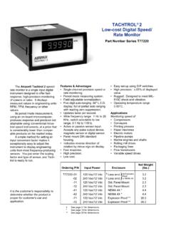
3 It will be superior in applica- Line Frequency Monitor Hz/. AC or DC power tions requiring fast update times and Hz Panel mount DIN housing high accuracies. As this instrument RS232 Speed Transmitter Net Weight Ordering P/N Input Power Enclosure (lbs.). T77310 -01. -02. -11. 120. 240. 120. Vac/24 Vdc Vac/24 Vdc Vac/24 Vdc }. Less Encl. Less Encl. For Explosion Proof or NEMA 4X. Std. Panel Mount -12 240 Vac/24 Vdc Std. Panel Mount -21 120 Vac/24 Vdc Splashproof Panel Mount -22 240 Vac/24 Vdc Splashproof Panel Mount -41 120 Vac/24 Vdc NEMA 4X * -42 240 Vac/24 Vdc NEMA 4X * -71 120 Vac/24 Vdc Explosion Proof ** -72 240 Vac/24 Vdc Explosion Proof ** It is the customer's responsibility to See page 21 for dimensions determine whether the product is * See page 19 for dimensions proper for customer's use and ** See page 20 for dimensions application. Operation (A-B)/A x 100 (% Slip) contains all of the constants neces- The TACHTROL 3 unit may be (B-A)/A x 100 (% Elongation) sary to define the conversion factors configured for measurement of a and instrument functions.
4 These single speed signal, two unrelated The TACHTROL 3 unit permits constants can be individually speeds or a speed with direction independent assignment of any of displayed and altered by a method indication (from an Airpax bi- these functions to any output similar to the setting of a Digital directional sensor). In addition, a (display, analog output and 1 or 2 clock. mathematical function may be setpoints). Additionally, the serial By utilizing a microcomputer as computed from two related Input Digital ouput may report on any or all the heart of the instrument, re- signals. These computed functions outputs continuously or on setpoint sponse time is improved tenfold are: alarm. All forms of relay logic are over the traditional EPUT (events Speed A (A + B)/2 (Average) field selectable. per unit time) tachometry. Further, Speed B A-B (Difference) The TACHTROL 3 unit is supplied this fast response time is attained A/B (Ratio) B/A (Inverse Ratio) with an electrically alterable read with no sacrifice in Digital accuracy.
5 A (Speed with direction) only memory (EAROM) which FIG. 1 FIG. 1 shows the CTW (constant thumbwheel switch), the DTW (digit thumbwheel switch) and the Pb (pushbutton). by which each digit may be entered or altered and a dip switch for selection of Input signal type for channel A or B. A battery is not necessary to retain the programmed constants. During normal operation, the DTW may be used to display Speed A, Speed B or the computed function. R31. Product Application one function for each output. Here are Analog output:Speed A. Guidelines the possibilities: RS232C: Transmit all values. The part number specifies the Setpoint 1: A/B. Outputs Selective Function hardware. Individual requirements for Function Relays setpoints, scaling and functions may be Each relay may operate on Input A, set into the instrument during installa- Display ------ Speed A Input B or the computed function. They tion. The following is a guide from Analog ------ Speed B may energize, de-energize, latch or which data to be entered may be Relay 1 ------ A-B auto-reset at the setpoint.
6 Hysteresis supplied. Relay 2 ------ A (dir.) (difference between setpoint value and Input Frequency A/B setpoint reset) is normally 5% but may Typically, an Input frequency is B/A be specified for any value from 1% to sensed from rotating gear teeth. (A + B)/2 99% of setpoint. Frequency may be obtained from RPM (A - B)/A x 100 A typical example for a TACHTROL 3. by the formula: (B - A)/A x 100 application is: f (in Hz) = RPM x PPR Input A: 2000 Hz = 800 FPM. If one of the outputs is not used, a tenth 60 Input B: 1600 Hz = 800 FPM. function, coded O, may be specified, where PPR = pulses per revolution = no. Display: A/B. turning the specific output off. of gear teeth. Analog output: Speed A=0-900 FPM. Analog Output =4-20mA. The normalization or scaling factor (SF). The zero and full scale for the analog Setpoint 1: Energize at ratio &. to be specified may now be obtained for output can be programmed to normal or above with 1% hysteresis each Input by: expanded scale, such as: Setpoint 2: Not used SF = DISPLAY VALUE (RPM,FPM, etc.)
7 4-20 mA = 0 to 900 FPM or Serial output: Transmit all values Input FREQUENCY (Hz). 4-20 mA= 450 - 900 FPM continuously. The desired form, as an example, is: Serial Digital Output This specific example is intended as Input A: 2000 Hz = 800 FPM The serial Digital (RS232C) output may a guide. The versatility of the TACHTROL 3. Input B: 1600 Hz = 800 FPM transmit the value on the display, the unit permits several approaches to Outputs analog output value, the two setpoint configuration. Unavailable information deviations or all four of these values. may be omitted as it could be supplied The TACHTROL 3 can transmit any of They may be continuously transmitted or during installation. More detailed the 6 computed functions, speed A, or transmitted on setpoint alarm. information is available in the TACHTROL 3. speed B, or speed A with direction to An example of the outputs specified is: Instruction Manual. any of the 4 outputs.
8 You may specify Display: A/B. Specifications Number range to 19999 Accuracy: (including temp. variations). Input Signals Three (3) LED function indicator lamps. Digital .03% typical ( .05% max.) &. Frequency: 2 Hz to 30K Hz 1 least significant digit Outputs Analog .3% of range Passive Sensor (sine wave): 200 mV to 25 Vrms standard 2K ohm Analog: 0-20 mA or 4-20 mA, field Response Times: impedance, common mode rejection: selectable, output consists of one 40 db, balanced Input sensitivity thousand 20 A steps. 750 ohm load Display updated approx. every 1/2 sec. measured at 1K Hz. maximum. Span pot-adjustable 10%. based on latest available Input Zero and full scale set into memory in measurement(s). Active Sensor (TTL): duty cycle 20 to engineering units. Serial Output: Transmits each output 80%, DC sensor power is 12 Vdc @ 100. 0-10 Vdc or 0-5 Vdc output obtained by value in approx. 1/2 second based on mA [will power two (2) zero velocity selecting the 0-20mA mode and using a Input measurements obtained at the time sensors or one (1) bi-directional sensor].
9 Resistor across the Input of the receiving each value is transmitted. Bi-Directional Sensor: One (1) instrument whose parallel combination Analog & Relay Outputs updated at a frequency Input (TTL Input A) and the with the Input resistance of the receiver variable rate depending on the fre- direction Input (TTL Input B)from a bi- is 500 ohms or 250 ohms respectively. quency. The typical & maximum directional sensor. [High (+5v) indicates response times are: positive direction, and only single speed Serial Digital : RS232C compatible Above 100 Hz = 100 ms typical functions (Speed A) are useful when transmit only ASCII. 300 baud. asyn- 200 ms max. connected in this operation mode.] chronous with odd parity. 2 stop bits and 2 to 100 Hz = 2 cycles + 30 ms typ. Power Supply carriage return. Transmission format 6 cycles + 30 ms max. 120 Vac 10%, 50-60 Hz selectable to transmit continuously or on Below 2 Hz =Measurement considered 0.
10 24 Vdc (23-30 V) std. 750 ohm analog any setpoint alarm. Transmission For values computed from both signal load or (20-30 V) with 600 ohm analog preceded by linefeed (Lf) and followed inputs, a new computed value is updated load. 15 watts maximum power. by carriage return (Cr). Each value each time either signal completes a consists of a space ( ), a two (2) digit measurement. Temperature: identifier, a colon and a right justified (7). 0 to 50 C operating character field of data (4 1/2 digit Range of Normalization (linear or -40 to 80 C storage number, sign and decimal) Plus (+) sign, inverse only). Humidity: and leading zeros indicated by spaces Input frequencies A & B may be normal- 90% relative and non-condensing (bbb). The following are examples of the ized by a number from .5000 x 10-7 to four (4) type transmissions: x 107. Vibration: Normalization is entered in the form: LfbDO:(display value) Cr Designed to meet MIL 810C, method +-1 XXXX.