Transcription of TACO ZONE CONTROLS WIRING GUIDE - TACO - HVAC
1 TACO ZONE CONTROLS WIRING GUIDE . Pages Switching Relays Single Zone WIRING 2 2. Switching Relays Oil Boiler WIRING Safety Notice 23 4. Switching Relays NON EXP Connected Together with Priority 5 11. Switching Relays EXP Connected Together with Priority 12 14. Switching Relays Multiple Indirect Hot Water Heaters 15 16. Switching Relays EXP Connected To Reset CONTROLS (PC700, 702 & 705) 17 28. Zone Valve CONTROLS NON EXP Connected Together with Priority 29 34. Zone Valve CONTROLS EXP Connected Together with Priority 35 38.
2 Zone Valve CONTROLS Connected To Reset CONTROLS (PC700, 702 & 705) 39 46. Hydro Air Fan CONTROLS (HAFC 101 & 201) 47 51. Specialty Thermostat and Zone Valve WIRING 52 56. Radiant Mixing Block 57 58. X-Pump Block 59 61. iSeries Mixing Valves 62 63. Low Water Cutoffs and Electric Water Feeders 64 79. Aquastat WIRING 80 86. Instruction Sheets 87 97. Standard Terms and Definitions 98. Cross Reference 99 100. Do it once. Do it right. Taco Catalog No. Effective Date: July 1, 2010. Supersedes Date: July 1, 2007.
3 TACO Zone control Product Information Switching Relays Product No. Description SR501 1 Zone Switching Relay SR501-845RP 1 Zone Switching Relay Replacement PC Board for Honeywell R845, RA89A, RA832 or Comparable Relay SR502 2 Zone Switching Relay with Priority SR503 3 Zone Switching Relay with Priority SR504 4 Zone Switching Relay with Priority SR506 6 Zone Switching Relay with Priority Switching Relays with PowerPort Options and Expandable to 20 zones Product No. Description SR501-EXP 1 Zone Switching Relay SR503-EXP 3 Zone Switching Relay with Priority and 3 PowerPorts SR504-EXP 4 Zone Switching Relay with Priority and 3 PowerPorts SR506-EXP 6 Zone Switching Relay with Priority and 3 PowerPorts Zone Valve CONTROLS Product No.
4 Description ZVC403 3 Zone Valve control ZVC404 4 Zone Valve control with Priority ZVC405 5 Zone Valve control ZVC406 6 Zone Valve control with Priority Zone Valve CONTROLS with PowerPort Options and Expandable to 20 zones Product No. Description ZVC404-EXP 4 Zone Valve control with Priority and 2 PowerPorts ZVC406-EXP 6 Zone Valve control with Priority and 2 PowerPorts Plug-In PowerPort Cards (For use with all -EXP CONTROLS ). Product No. Description PC600 Post Purge Timer Plug-In Card PC605 Priority Protection Plug-In Card PC610 Universal Timer/Pump Exercise Plug-In Card Add-On Power CONTROLS (For use with all -EXP CONTROLS ).
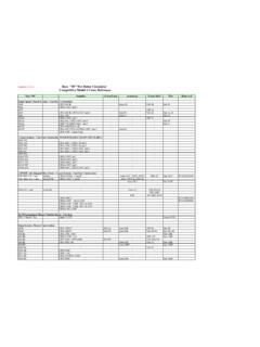
5 Product No. Description PC700 Boiler Reset control PC702 2-Stage Boiler Reset control PC705 Variable Speed Pump Injection Mixing control Fan CONTROLS Product No. Description HAFC101 Hydro Air Fan control HAFC201 Hydro Air Fan control with Optional Time Delays Do it once. Do it right. 2. SR501 Switching Relay WIRING TYPICAL WIRING ALTERNATIVE WIRING ALTERNATIVE WIRING . (COLD START) (TANKLESS COIL) (24 VAC POWERED INPUT SIGNAL). THERMOSTAT THERMOSTAT. T T 24 VAC. SIGNAL. SR501 SR501 SR501. 1 ZONE 24 1 ZONE 24 1 ZONE 24.
6 SWITCHING RELAY R W VAC SWITCHING RELAY R W VAC SWITCHING RELAY R W VAC. T T COM T T COM T T COM. POWER POWER POWER *. T STAT T STAT T STAT *. 120 VAC 120 VAC. INPUT INPUT. N H 3 N/O N/C N/C N/O. 4 4 6 6 5 N H 3 N/O N/C N/C N/O. 4 4 6 6 5 N H 3 N/O N/C N/C N/O. 4 4 6 6 5. JUMPER. TO: ZC. TO: TT ON BOILER TO: ZR TO: TT ON BOILER. H. TO: 120 VAC POWER. N. TO: 120 VAC POWER. CIRCULATOR CIRCULATOR CIRCULATOR. TO: 120 VAC. POWER. Note: When using Alternative WIRING diagram, the boiler oper- REMOVE JUMPER.
7 * T STAT LIGHT WILL GO. ating control 's ZC terminal will see the load of the circulator(s). DO NOT CONNECT POWER ON AND OFF WITH 24 VAC. Warning: When using Alternative WIRING diagram, WIRING TO N AND H TERMINALS. SIGNAL. POWER LIGHT. instructions must be followed so power originates from the boiler WILL ALWAYS BE OFF. aquastat. Failure to follow these WIRING instructions may result in a secondary source of power being connected to the boiler that may activate it under certain circumstances, causing injury or death.
8 NOTE: No tankless coil priority. 3. (cont.). L1 L2. THERMOSTATS. (HOT) (NEUTRAL). CIRCUIT THERMOSTAT. BREAKER. ZONE 4. PRIORITY. ON. SR 504 OFF. ZONE 1 ZONE 2 ZONE 3 ZONE 4. CUSTOMER. EMERGENCY FOUR ZONE SWITCHING RELAY L1 L2 T T. WITH OPTIONAL PRIORITY. SWITCH. HONEYWELL L8124. POWER. ZONE 1. OR EQUAL. ZONE 2. C1 ZC. THERMAL ZONE 3. FUSE ZONE 4. B2 C2 ZR B1. (FIROMATIC) 24 VAC 120V RELAY. POWER. X X ZONE1 ZONE2 ZONE3 ZONE4 POWER. END ZC ZR. SWITCH 120 VOLT CIRCULATORS INPUT CIRCULATOR. ON BOILER. (IF ATTACHED).
9 SERVICE. FUSE 1 AMP. SWITCH. LINE VOLTAGE. OIL BURNER RELAY. LOW. WATER. CUTOFF. 120 VAC INPUT. NOTE: Tankless coil has priority. L1 L2. (HOT) (NEUTRAL) THERMOSTAT. CIRCUIT THERMOSTAT. BREAKER. 24 VAC. POWER. SR 503. ZONE 1 ZONE 2 ZONE 3. CUSTOMER. EMERGENCY THREE ZONE SWITCHING RELAY L1 L2 T T. FUSE 1 AMP WITH OPTIONAL PRIORITY. SWITCH. HONEYWELL L8124. POWER. ZONE 1. OR EQUAL. ZONE 2. C1 ZC. THERMAL ZONE 3. FUSE B2 C2 ZR B1. (FIROMATIC). ZONE1 ZONE2 ZONE3. X2. N P ZC H X1 ZR 120 VOLT CIRCULATORS CIRCULATOR.
10 ON BOILER. (IF ATTACHED). SERVICE. SWITCH. LINE VOLTAGE. OIL BURNER RELAY. LOW. WATER. CUTOFF. 120 VAC INPUT. NOTE: The boiler operating control 's ZC terminal will see the load of the circulator(s). 4. SR502/503 Switching Relay Controlling Another SR502/503 Switching Relay AQUASTAT. ON DHW A T T. HEATER. MASTER. 24 VAC. POWER. PRIORITY ON. VIA JUMPER. PLACEMENT SR 503 ZONE1 ZONE2 ZONE3. THREE ZONE SWITCHING RELAY. WITH OPTIONAL PRIORITY. FUSE 1 AMP. POWER. ZONE 1. ZONE 2. ZONE 3. X2. N P ZC H X1 ZR ZONE1 ZONE2 ZONE3.