Transcription of Tank Weighing Woes - Sawyer/Hanson
1 Tank Weighing woes : Why Load Cells have a Bad Reputation and what needs to be done to fix it Written by Ryan Titmas, Product Manager, Sartorius North America I cannot tell you how many manufacturing facilities currently have load cells installed in tank systems that are no longer operational. Most of the times the load cells are left in place and the electrical cables connecting to the controls are simply cut. Production Managers, QC Managers, and maintenance personnel alike have surely encountered that tank or vessel which never weighed correctly. Why? Why have so many switched from a supposedly higher accuracy load cell solution to old fashioned level probes or site glasses to determine tank contents? There are several major causes, all of which will be highlighted within this brief paper. Don t worry your not alone and be assured that some simple knowledge and consultation will help you better understand the root cause of your vessel Weighing dilemmas.
2 The Beginning Ok, I am an engineer and I must admit before I specialized in load cell solutions I could care less what type of load cell was specified under a tank during project design phases. Pick a load cell from the local catalog; mount one under each leg, and bingo, a perfect Weighing system. The only science involved is finding the vessel dead-weight , specific gravity of the product, and then estimate the total weight. Easy design, simple drawing integration, no need to worry about load cells, time to move on. Improper specification of load cell systems is not due to incompetence by the engineer, rather lack of education on load cell Weighing systems and what real life factors effect these installations. Some simple mechanics, installation tips, and real life lessons found in this paper will help give design engineers some tips on correctly integrating load cells in the future. QC Managers, Production Managers, and other production personnel will also learn some tips on correcting their existing tank or hopper installations.
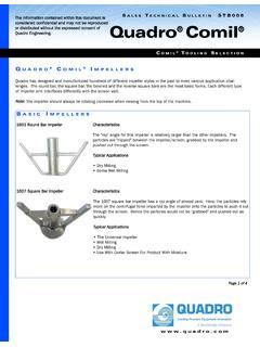
3 Mechanical Properties of the Problem: Shear Beam Load Cell Shear beam load cells are general force sensors and cannot discriminate against true vertical load and side/torque loading. The idea of a load cell system is to capture the true vertical load or the weight within the tank, however real world conditions or improper installation will cause the load cells to see much more than vertical loading. These other factors are what causes un-repeatability in Weighing and ultimately leads to load systems being dismantled. Before learning about the factors that cause inaccurate tank Weighing it is important to learn how a shear beam actually works. A shear beam load cell is basically a precision milled piece of stainless steel that has electronic sensors called strain gages adhered to it. The strain gage is positioned at a 45 degree angle to measure the steel shear strain. Illustration A shows the positioning of the strain gages on the shear beam load cell.
4 Figure A Hygienic Bench Scale with Bending Beam Cell Installed Strain gages are zigzag-shaped strip conductors, etched from thin metal film. They use the effect of the change that the electrical resistance of a conductor will undergo when it is subjected to mechanical stress (the change in resistance is caused by a change in length, cross section and specific resistance). The letter F in the above picture shows the required force introduction point on the load cell. The body of the load cell is typically constructed of a mild steel, stainless steel alloy or aluminum. A typical load cell will undergo thousands of Weighing cycles, so the composition of the metal is very critical in producing accurate Weighing results. A Shear beam load cell is actually measuring the shear strain of steel which occurs, so if the steel itself is not monolithic throughout, errors in Weighing and load cell failures will occur. In general it is critical that load cell manufacturers obtain steel and aluminum that is high grade to produce the best Weighing results.
5 Why Beams don t typically work in industrial vessel Weighing Bending beam and shear beam load cells are the industry standard for bench and floor scales. Next time you have a free moment, lift up the pan and look underneath a scale, more than likely you will find some type of bending beam load cell. (See Figure A) If these types of load cells are used in bench scales then why can t they be used in vessel Weighing tasks? Scales and balances are self contained units that rarely encounter the extraneous side forces and environmental influences vessels do. Yes, it is true that scales are subject to environmental factors, however not to the extent of process vessels. The fact is that bending beam load cells are perfect for environments where typical static Weighing will take place; they are not intended for process vessel applications. Vessel Weighing applications require a load cell and mechanical support system that will eliminate non-vertical loading and produce reproducible Weighing results.
6 Illustration A: Shear Beam Cell strain gauge positioning, F indicating load introduction Fixing the Problem: First thing first, a vessel or tank Weighing application will never be successful if the actual tank construction is not adequate. What do I mean by adequate? Well, when vessels are designed they are designed to adequately and safely hold product, withstand environmental issues such as wind, earthquakes and other forces of nature. The idea that the vessel needs to weigh accurately is generally an afterthought in the design process of a tank. The most important thing to remember with tanks is the construction of the Weighing frame or frame where the load cells will be mounted. This frame mechanically connects all load cells under the vessel and ensures that they cannot move in different directions independently of each other. Since the load cells only transfer vertical compression forces (compression load cells will be discussed later in the paper) the design has to ensure that in case of external forces the load cells cannot tilt.
7 Figure B shows the best type of installation. Notice how the load cells are placed in the middle of the beams and that the load cells are situated between (2) two frames. This frame network ensures the load cells will move together, creating a more repeatable Weighing environment. In Figure B the load cells are mounted on top of a bottom frame assembly which provides a good rigid and stiff foundation. Remember that the weight of the vessel is being transferred to the load cells and then to the bottom frame. With this in mind it is critical that this transfer of force is carried out with minimal deflection. Please also note that Figure B Compression Load Cells Installed properly in a double frame design VESSEL Load Cells Figure C Vessel illustrated with long legs and poor cross-bracing will generally produce poor Weighing repeatability Figure D Vessel illustrated with shorter legs and a top/bottom frame construction.
8 Good rigidity and cross bracing will produce excellent Weighing accuracy. the load cells can be mounted directly to the floor without the bottom frame, however the construction of the floor must allow little deflection and settling. The load cells are measuring deflection down to thousands of a millimeter, so if your foundation deflects, you are not going to achieve acceptable accuracy. Figure C illustrates another design problem typically found in tank Weighing applications. It shows load cells installed on the end of very long tank legs. This type of installation will typically cause Weighing errors due to the separate legs moving in different directions. Repeatability problems due to the variability in movement and drift concerns caused by the extraneous deflection. Figure D illustrates a good load cells installation because the legs from the tank are shorter, minimizing separate leg movement, and the load cell has a top and bottom frame to help induce a more uniform loading pattern.
9 Please note that these illustrations show only examples and each Weighing applications is different) Rigid tank construction with a solid foundation, got it, but what other tank design factors must be considered? One of the most overlooked factors is the vessels peripheral connections and accessories, such as pipes, mixers, ladders, walkways, etc. Each of these external fixtures carries a specific influence on the Weighing system that must be addressed. Pipes entering and exiting a vessel are always exerting forces on a vessel and create no real problem under stable ambient conditions, constant temperature. We all know Figure E: Illustrates the various forces reacting between hard-piping and a vessel. that industrial applications are far from ambient thus pipe expansion, and movement will adversely affect Weighing results. To better visualize this effect simply stand on your bathroom scale and take your weight reading (don t worry I don t like what it reads either!
10 Next weigh yourself by gently pushing on the wall, and then once more by pulling on a nearby towel rack. The results are different aren t they? This type of action/reaction force is similar on vessel Weighing applications where pipes are present. A simple way to dampen the effects of pipes on Weighing measurements is to have all pipe connections enter from the side. (If possible) Pipe hangers should be placed as far away from the tank as possible to allow for flexing as the tank moves up and down during loading. Flexible pipe connections and bellow can also be used to connect hard pipe to the vessel, however ensure the flexible connections are truly flexible. (A 1 flex joint on a 4 inch pipe probably isn t effective) Figure E illustrates the possible forces and displacements of piping: a rigid pipe can lift some weight off the vessel and cause a displacement ( P) A force Fp along the pipe can push the vessel to the side and exert forces downward or vise versa.