Transcription of Tech Tip: Steering Geometry - OptimumG
1 tech Tip: Steering GeometryDesigning Steering GeometryWhen you re designing Steering kinematics, the goalis to orient the tire to the road in the optimal orienta-tion. But, how do you know the optimal orientation?Tire data, of course!One of the basic decisions when designing a steer-ing system is how much Ackermann you want. Theanswer to this is determined directly by the tire char-acteristics, and you can answer this question by us-ing OptimumT in a clever , let s try it! We will design the Steering geom-etry for a small autocross car (210kg) as an data that we ll use was collected at Calspan bythe FSAE TTC (Tire Testing Consortium).
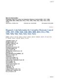
2 Sincewe re using a race car for the example, our goal is togenerate the maximum lateral force from the ll start by taking raw tire data that was collectedon a tire testing machine and import it into Opti-mumT. Next we ll fit a Pacejka 2002 tire model tothis data using the OptimumT Model Fitting more information about this process, please re-fer to the OptimumT documentation. What we endup with is shown in Figure we have a tire model, we can use Opti-mumT s visualization tools to look at some derivedquantities. We can also use the OptimumT Add-Into directly incorporate the tire model into Excel orMatlab. We ll look at the slip angle at which thepeak lateral force occurs at different loads and cam-ber angles.
3 This will allow us to design the steeringgeometry to suit the tire. Before we get to that, how-ever, we need to find the vertical load and camber ofeach of the front wheels. We ll do this in two steps:first using a simple method, then a more Steering GeometryIf, for a moment, we ignore the camber of the fronttires, we can find the desired Ackermann angle veryeasily. We need to estimate the maximum lateral ac-celeration that the car can achieve. We can do thisby constructing a simple weight transfer spreadsheetand by using OptimumT. We need to know the massof the car (for now we ll ignore the non-suspendedFigure 1:Tire data and modelweight transfer), the CG height, the weight distribu-tion, the front and rear roll stiffnesses and the this example, the vehicle configuration usedis shown in Table (m)210kgWeight Distribution ( )45%frontCG Height (h)140mmFront Track (tf)1300mmFront Roll Stiffness (Kf)220Nm/oRear Roll Stiffness (Fr)200Nm/oTable 1: Basic vehicle parametersTo calculate the lateral weight transfer, we ll usethe following formulas.
4 Mroll=Aymh(1) roll=MrollKf+Kr(2)Fzr= mg+ rollKftf(3)Fzl= mg rollKftf(4)Ay=(Fyr+Fyl) m(5) Ayis the lateral acceleration Mrollis the roll moment rollis the roll angle1 tech Tip: Steering GeometryFigure 2:Maximum lateral force versus load FzrandFzlare the right and left tire verticalloads FyrandFylare the right and left tire lateralforces gis the acceleration due to gravityWe ll perform an iterative calculation to find themaximum lateral acceleration using the equationsabove. Using Figure 2, we will also use them to findthe vertical load on the two front tires. This verticalload will be used to find the ideal slip angle.
5 We findthat the right tire has a vertical load of686 Nandthe left tire has a load of241N. In these calcula-tions, we implicitly assume that the front axle is thelimiting axle; thus the car has terminal can use OptimumT to plotIdeal Slip Angleversus Normal Load(Figure 3). By picking out theslip angle at the two vertical loads that we calculatedearlier, we find that the outside tire should angle and the inside tire should This can be used to find the appropriatesteering Geometry , and indicates that that the carneeds positive Advanced Steering GeometryWe can improve the calculations by including thecamber. We could do this by using graphs created inFigure 3:Ideal slip angle versus loadFigure 4:Example of OptimumT Add-In use in Ex-celOptimumT, but an easier way is by using the Opti-mumT Add-In.
6 This allows you to make calculationswith OptimumT inside Excel or Matlab. For exam-ple, if you want to find the lateral force calculatedby a tire model that you created in OptimumT, youcan easily do this with the OptimumT Add-In. Thisis shown in Figure find the desired Steering Geometry , we can cre-ate a new spreadsheet in Excel that calculates thelateral weight transfer when both front tires are gen-erating the peak lateral force. The finished spread-sheet is show in figure same formulas used in the simplified calcula-tions for the weight transfer are used here. In thesecalculations, we can use the OptimumT Add-In tofind the maximum lateral force that the tire can gen-erate.
7 We use the OptimumT Add-In function:CalculateFyPeakNegative()2 tech Tip: Steering GeometryFigure 5:Ackermann design spreadsheet3 tech Tip: Steering GeometryBy using this function in the Excel spreadsheet,we can automate the process of finding the maximumlateral acceleration. We create a "circular reference"in the spreadsheet and Excel will automatically per-form an iterative complete the rest of the calculation, we needa little bit more information about the vehicle. Forthis example, we use the following vehicle parame-ters. The parameters given earlier still (l)1650mmCamber Coefficient (C) Camber ( 0) 2oCaster ( )6oKPI ( )2oTable 2: Vehicle parameters required for advancedanalysisOnce we have these values, we can expand thecalculations preformed earlier by taking into accountthe camber of the two steered wheels.
8 Includingcamber in the calculations increases the accuracy be-cause we include the camber thrust when finding thepeak lateral forces. We calculate the inclination an-gles as follows: r= r0+ (1 cos r) sin r+ rollC(6) l= r0 (1 cos l) sin l rollC(7) rand lare the right and left inclination an-gles rand lare the right and left steered angles(found later)The slip angles at which the peak lateral force oc-curs can be calculated using the OptimumT is dependent on vertical load and the inclinationangle. The function used is:CalculateSAPeakNegative()We use geometric relationships to find the slipangles of the front wheels when they are not is used to calculate the required steered angleof the two front wheels.
9 The geometric slip angleof the two front wheels can be closely approximatedwith the following expression: Gr=lR+t2+ (8) Gl=lR t2+ (9) Grand Glare the right and left geometric slipangles Ris the turn radius is the body slip angleWe find the ideal steered angle of the two steeredwheels using the following formula: r= Gr ir(10) l= Gl il(11) irand ilare the ideal right and left slip angles rand lare the required right and left steeredanglesWhere the ideal slip angle is calculated with theOptimumT these equations depend on the turn radius,we repeat them for multiple steer angles. Since we redesigning the Steering Geometry , we re interested inthe difference in steered angle between the inside andoutside wheel.
10 When we take the difference in leftand right steered angle, the body slip angle will can-cel now have the difference in left and right steeredangles versus turn radius. We re trying to designsteering Geometry , though, so we would prefer to plotthis versus some Steering angle. We ll assume thatthe car will be close to neutral steer, so the Acker-mann Steering angle relationship holds ( ack=l/R).The difference in left and right steered angle plot-ted against the Ackermann Steering angle is shownin Figure 6. This gives us a target curve when wedesign the Steering we read this graph, we find that these tires,fitted on this particular car, need positive Acker-mann.