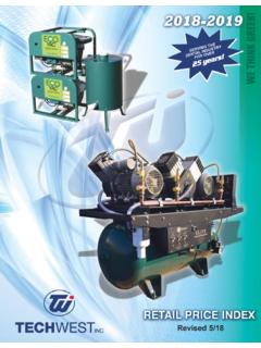
Transcription of TECH WEST INC.
1 2625 N. Argyle Ave. Fresno, CA 93727(559) 291-1650 (800) 428-7139 FAX (559) 348-9677 tech west of Dental Vacuumand Air Systems2625 N. Argyle Ave. Fresno, CA 93727(559) 291-1650 (800) 428-7139 FAX (559) 348-9677 tech west of Dental Vacuumand Air SystemsWHIRLWIND VACUUM PUMPINSTALLATIONAND SERVICEMANUAL Revised 4-151 WHIRLWIND PUMPINSTALLATION AND SERVICE MANUALThis manual is for the installation and service of tech west s WhirlWind 1: Plumbing Schematic4 Figure 2: Water Connection4 Figure 3: Typical Dual WhirlWind Installation5 Figure 4: Sink Cabinet Installation5 Figure 5: Vacuum Connection - Single WhirlWind6 Figure 6: Vacuum Connection - Dual WhirlWind6 Figure 7: Wiring Diagram7 Figure 8: Remote Control Wiring7 Figure 9: Line Voltage Connection8 Weekly Servicing9 Parts List10-16 TROUBLESHOOTINGS ingle Vacuum Pump Troubleshooting18-19 Dual Vacuum Pump Troubleshooting20-21 Triple Vacuum Pump Troubleshooting22-23 Installation Diagrams and Information24-26 Maintenance & Service and Notes Sheet27-29 WHIRLWIND LOCATION REQUIREMENTSThe WhirlWind location should be level, accessible and well the WhirlWind will be located in a confined space, provide cross ventilation and install an exhaust following utilities are required:(a) Cold Water SupplyInstall a separate 1/2 cold water branch for the WhirlWind water intake(s).
2 This will cool and lubricate the shaft seal. Water pressure should be between 25 and 55 psi (water must remain on during operation) or shaft seal damage will occur.(b) Waste DisposalThe WhirlWind will exhaust both vapor and liquid waste. Provide exhaust vent sized to 2 in diameter and a waste drain which complies with local code.(c) Vacuum LineThe main vacuum line from the operatories must connect to the WhirlWind vacuum pump intake manifold.(d) Electrical(1) Line voltage must be within the limits of Table 1 below. (Install a buck-boost transformer if line voltage is not between these values.) Provide a separate line for each pump motor. Circuit breaker switches must be 20 amp.(2)Local code may require you to provide one quick disconnect (safety switch) for each pump motor.
3 (3)The WhirlWind is controlled by a 24 volt circuit. For remote control, provide one 18/3 jacketed cable for each pump VOLTAGE RATING230 v115 vMIN VOLTAGE RATING208 v constant110 v constantMAX VOLTAGE RATING240 v constant130 v constantTABLE 1 WHIRLWIND STEPS(a) Check the shipping carton for damage. This could detect damage to the unit which might otherwise be overlooked.(b) Remove the WhirlWind from its shipping carton. Inspect the unit for damage. (Single WhirlWind s are shipped bolted to a pallet. This pallet is intended for shipping use only and should be discarded).(c) Inventory your Hook-Up Kit. Check its contents against the inventory sheet included. These items will be used in the remaining steps.(d) Mount the WhirlWind. To dampen vibration, ensure rubber isolators are installed on each WhirlWind to the schematic diagram of Figure 1 for steps (e) (f) and (g).
4 (e) Connect the cold water supply. See Figure 2. Turn the water on and check for leaks in the water control assembly.(f) Make the necessary waste connections. Figures 3 and 4 show typical installations. To install a tech west Exhaust Separator or Water Recycler see the applicable installation sheet.(g) Connect the main vacuum line. For Single WhirlWind s, connect flexible hose to the pump intake manifold (Figure 5). For Dual and Triple WhirlWind s, connect to the vacuum intake manifold(Figure 6).Refer to the wiring diagram of Figure 7 for steps (h) and (I). Detailed wiring diagrams are on the inside of each pump relay panel cover plate.(h) Connect remote control 18/3 jacketed cable to each pump relay panel. Use wire connectors which provide secure mechanical connections. See Figure 8.
5 (i) Connect to line voltage (via safety switch(es) if required by local code). Use 12 gauge THHN grade wire and approved conduit for permanent wiring. See Figure 9. (Single WhirlWind pumps may operate on either 115 volt or 230 volt lines. For terminal changing instructions see inside of relay panel cover plate.(j) Turn on the WhirlWind. Check the pump(s) for leaks and the vacuum level following the instruction in Weekly Servicing page Blue HoseBall ValveBrass AdapterBrass Close NippleBrass BushingFigure 1: Plumbing Schematic1. Line Filter4. Impeller7. Exhaust Vent2. Cold Water Supply5. Solenoid Valve8. P-Trap Adapter3. WhirlWind Pump6. Exhaust Separator9. Waste LineFigure 2: Water Connection5 VentilationFloorSinkExhaustSeparatorFrom OperatoryFanExhaustVentCold WaterSupplyMainVacuumLineSafetySwitchSaf ety SwitchExhaustVentExhaustSeparatorColdWat erSupplyP-TrapAdapterFigure 3: Typical Dual WhirlWind Vacuum InstallationFigure 4: Sink Cabinet Installation6 Figure 5: Vacuum Connection For Single WhirlWind PumpFigure 6.)
6 Vacuum Connection For Dual WhirlWind PumpGLUE ALL EXHAUST HOSE CONNECTIONS SECURELYWITH PVC GLUEPump OneDual CheckValve AssemblyHose ClampMainVacuumLinePump Two3/4 FlexiblePVC HoseMain VacuumLine3/4 CouplingMale Adapter (PVC GLUE ALL HOSE CONNECTIONS EXCEPT THIS ONE)LineFilter7 RelayPanelWireConnectorsToRemoteControlP anel230 vSafetySwitches18/3 JacketedCableCircuitBreaker230 v230 vNuet24 V Remote Control PanelWhirlWind OneWhirlWind Two24 VRemoteControlRelay24 8: Remote Control WiringFigure 7: Wiring DiagramWiring Diagram IllustratesThe Connections For a Dual WhirlWind Pump8 Figure 9: Line Voltage ConnectionsConduitFromSafetySwitchGround ConnectionTerminalBoardRelayBoxMotorLead sLoadOutLineInLoadOutLineInWHIRLWIND PUMPWEEKLY SERVICINGR efer to Figure 10 for the following steps.
7 (a) Clean vacuum filter bowl and screen. Turn the pump off and unscrew the vacuum filter bowl, rinse bowl and screen under cold water. Replace bowl or screen if damaged. Ensure gasket is in place in the filter bowl before reassembly.(b) Flush the WhirlWind pump(s) and main vacuum lines with a non-foaming dental vacuum cleanser. Follow the cleanser manufacturer s instructions.(c) Visually inspect WhirlWind pump(s) for water leakage. Ensure that all hose clamps and water connections are tight.(d) Check vacuum gauge level. Vacuum settings are adjusted at the factory according to table 3 below. To check the vacuum level, ensure that the pump is aspiring air only. If the vacuum level is out of adjustment, turn off the pump and remove the vacuum relief valve. Holding the phillips head screw in place, turn the tension nut.
8 One complete clock-wise turn of the tension nut will add 2 in. hg. to the vacuum level; one complete counter-clock-wise turn will subtract 2 in. hg. from the vacuum : NEVER SET VACUUM LEVEL HIGHER THAN INDICATED IN TABLE 3 Flush the entire vacuum piping system (all operatories) weekly. Use a non-foaming cleanser. If the WhirlWind cannot induce adequate air flow because of a blockage in the vacuum piping system, liquids and solids will not evacuate. Contact tech west s Customer Service for further details on maintaining your vacuum piping (HORSEPOWER)AIR ASPIRATION VACUUM LEVEL(INCHES OF MERCURY)TABLE 31101 1/212212102458109163 KEYPART PUMP IMPELLER 1 1/2 HP PUMP12 WIA-100 WATER INJECTION ASSEMBLY, COMPLETE13 PRC-100115V/230V RELAY CONTROL BOX, COMPLETE14 BPHBRASS PUMP HOUSING15 PSS-100 SHAFT SEAL16 BISBRASS PUMP IMPELLER 1 HP PUMP17 BILBRASS PUMP IMPELLER 2 HP PUMP18OR-55 RUBBER BASE PLATE 0 RING SEAL19 BBP BRASS BASE PLATE110 RFV-100 RUBBER FEET FOR VACUUM PUMP3 WHIRLWIND PUMP * 1 HP - 1 1/2 HP - 2 HP711 KEYPART VACUUM BREAKER112 BRN-4-21/4 MPT x 1/8 MPT NIPPLE113 PSV-115GC115V 1/8 SOLENOID VALVE/COIL114BN-125-CL1/8 BRASS CLOSE NIPPLE115 VPS-1251/8 WATER X 1 1/2 BRASS NIPPLE117 PRT-2501/4 BLUE POLY TUBEPER.
9 FT18 WIN-RP1/4 MPT INJECTION NOZZLE (FOR RECYCLERS ONLY)119 WIN-2P1/4 INJECTION NOZZLE1 WATER INJECTION ASSEMBLY15141312111718161912 WHIRLWIND MANIFOLD AND FILTERKEYPART HG GAUGE119BN-750-CL3/4 BRASS CLOSE NIPPLE120 VFA-403/4 FILTER UNIT, COMPLETE121 VFG-1003/4 RUBBER GASKET FOR BOWL322 VFS-4040 MESH SCREEN FOR 3/4 FILTER323MG-100 MANIFOLD GASKET124 VRV-100 VACUUM RELIEF VALVE W/ FITTING125 VFB-1003/4 VACUUM FILTER BOWL126 VPMA-100 MANIFOLD ASSEMBLY, COMPLETE1202122252419231813 KEYPART HOLDER, PUMP128 SBF-2501/4 AMP SLOW BLOW FUSE529PT-10024V TRANSFORMER, 30A130PR-10024V RELAY CONTACTOR1-RC-115115V RELAY CONTROL, COMPLETE1-RC-230230V RELAY CONTROL, COMPLETE1 LOW VOLTAGE RELAY CONTROL BOX2728293014 KEYPART FEET FOR VACUUM PUMP333 PTA-100P-TRAP ASSEMBLY134ES-1 EXHAUST SEPARATOR TANK 139 CVF-7503/4 CHECK VALVE 1 SINGLE WHIRLWIND34393233 SINGLE PUMP UNITS REQUIREEXHAUST SEPARATOR TANKTO MOUNT TO A BALL VALVE / FRESH WATER SUPPLY232 RFV-100 RUBBER FEET FOR VACUUM PUMP436 DCV-100 DUAL CHECK VALVE ASSEMBLY133 PTA-100P-TRAP ASSEMBLY135ES-2 EXHAUST SEPARATOR TANK139 CVF-7503/4 CHECK VALVE2 DUAL WHIRLWIND PLATFORM393336323516 KEYPART BALL VALVE / FRESH WATER SUPPLY332 RFV-100 RUBBER FEET FOR VACUUM PUMP637 TCV-100 TRIPLE CHECK VALVE ASSEMBLY133 PTA-100P-TRAP ASSEMBLY138ES-3 EXHAUST SEPARATOR TANK139 CVF-7503/4 CHECK VALVE3 TRIPLE WHIRLWIND PLATFORM393338323717 Maintenance & Service SuppliesService scheduled for.
10 Service items needed:18 DOES VACUUMPUMP RUN?Is there sufficientsuction?Is there excessivevacuum?Does pump runcontinuously?YESYESNODoes thermal protector shut thepump down?NOYESNOIs vacuum relief filter clogged?Is vacuum relief filter or intakestrainer screenclogged?Check foradequateventilationand ON TOTHE orreplacefilterAre there anyvacuum leaks atthe pump?Is the officevacuum pipingsystem faulty?Is the vacuum reliefvalve set too low?(Normal level is 10 hg)Is there adequatewater supply orwater pressure?Is vacuum reliefvalve set too high(above 10 hg)?Is circuit breakertripping?Do relay contactsremain closed?Adjust to10 relay to10 vacuum inletline frompump. Ifthere is goodsuction atpump, but little or nonein system,the system isclogged orcontains sized or defective Check for proper wiregauge size.