Transcription of Technical data MTL surge protection EPS 01-107 Rev V MTL ...
1 June 2017 EPS 901-107 Rev VTechnical data MTL surge protectionEaton Electric Limited, Great Marlings, Butterfield, LutonBeds, LU2 8DL, : + 44 (0)1582 723633 Fax: + 44 (0)1582 422283E-mail: 2017 Eaton All Rights ReservedPublication No. EPS 901-107 Rev VJune 20171 The SD range is a series of surge protection devices combine unparalleled packing densities, application versatility, proven reliable hybrid circuitry, simple installation and optional loop disconnect facilities features which make the range the ultimate surge protection solution for process equipment, I/O systems and communications exceptionally high packing densities are the consequence of an ultra slim footprint for individual modules which can thus double-up as feedback terminals. Each module provides full hybrid surge protection for 2 and 3 wire loop with a comprehensive range of voltage ratings cover all process related signals such as RTDs, THCs, 4 to 20mA loops, telemetry outstations, shut-down systems and fire and gas loop disconnect , is a feature which allows commissioning and maintenance to be carried out without removal of the surge protection device.
2 This facility is provided by the SD07, SD16, SD32 and SD55 units. In addition, a third connection on the field and safe side of the protector is provided in order to terminate screens SD rangeUltra-slim user-friendly devices for protecting electronic equipment and systems against surges on signal and I/O three wire applications the specially designed SDRTD (Resistance Temperature Detector) and the SD32T3, (for separately powered 4-20mA loops) provide full 3-wire protection in a single compact unit. The recommended choice for the protection of 3-wire pressure transducers on low power circuits is the higher bandwidth applications, the SDR range has been developed to meet the demands of today s highest speed communication and 240V AC versions are available for I/O and power supplies up to three Amps of load current and telephone networks can be protected by the simple manual operation clamps modules securely onto DIN rail, which automatically provides the essential high-integrity earth connection.
3 Top-hat (T-section) DIN rail is generally suitable for mounting SD modules although for adverse environments, a specially-plated version is available. A comprehensive range of mounting and earthing accessories can also be supplied, see page 7 for further details. Range of ATEX Certified intrinsically safe surge protectors Ultra-slim space-saving design; easy installation Multistage hybrid protection circuitry 20kA maximum surge current Range of voltage ratings to suit all process I/O applications High bandwidth, low resistance, RTD, PSTN and 3-wire transmitter versions available 10 year product warrantyMTL SD rangeJune to applications and selection The SD range of SPDs includes models for almost all possible applications operating at voltages up to 250V AC. The optional fuse/disconnect package provides both fused protection against fault currents and a convenient method of isolating field circuitry from protected circuitry without needing additional disconnect terminals.
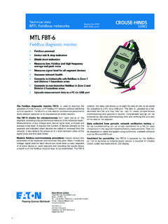
4 The standard fuse (which is replaceable) is rated 250mA with 50mA fuses also being available by special request. Where only the disconnect feature is required, solid links can be an example, this feature is of particular value in applications in which an SPD is used with a bulk power supply feeding multiple loops. The individual module fuse prevents a fault or follow on current on one loop disrupting the power supply to the others. Also, loops can be removed from the circuit for maintenance reasons or added without needing additional disconnect terminals. The following guide to selection suggests the most suitable SDs for a number of specific applications. For Technical information, see the detailed specifications on the back page of this publication (some field circuit protection is shown for completeness).FIELD CIRCUITPROTECTED CIRCUIT2-wire transmitters3-wire RTDsPhotocells, THCs, mV sources and turbine flowmetersAnalogue inputs (high-level)2-wire transmitters, 4-20mA, conventional and smartThe SPDs recommended for use with conventional and smart 4-20mA transmitters (fed by a well-regulated supply) are the SD32 and SD55, the choice depending upon the maximum working voltage of the system (32V and 55V respectively).
5 The diagram illustrates a prime example of an application for which the fuse/disconnect facility is particularly useful, however, both models are available in X versions without the optional fuse/disconnect inputs (low-level)RTDsThese applications are best served using the SDRTD. For optimum accuracy, the energising current should be chosen to ensure the voltage across the RTD does not exceed 1V over the full measurement range. When using a PT100 device, we recommend an energising current of , THCs, mV sources and turbine flowmetersThe SD07 or SD16 (depending upon the operational voltage) are the favoured choices for this application. SD07X and SD16X are also SD rangeJune CIRCUITPROTECTED CIRCUITC ontroller outputs(I/P converters)SwitchesAlarms, LEDs, solenoid values, linePLC, I/O systemsAnalogue outputsController outputs (I/P converters)For this application, the recommendations are the SD16, SD32 and SD55 (and the equivalent X versions), the final choice depending upon the operating (on/off) inputsSwitchesSuitable SPDs for switches include the SD07, SD16, SD32 and SD55 modules the choice depending upon the operating voltage of the system.
6 The X versions of these are also (on/off) outputsAlarms, LEDs, solenoid valves, etcAlarms, LEDs, solenoid valves, etcThe recommended choice for this application is the SD32 or (PSTN)Telemetry outstationsThe SDPSTN has been designed specifically for the protection of signals transmitted on public switched telephone supplied equipmentPLC, I/O systemsFor systems on 110-120V ac, the SD150X is the recommended choice and for 220-240V ac systems, the SD275X is SD rangeJune and sensor protection Transmitters and sensors are widely used in highly exposed areas and where lightning damage is common. In many cases, the ideal solution for 2-wire transmitters or sensors is the TP48 which mounts directly onto the transmitter housing via spare cable entries. Where these entries are not available or 3-wire devices are used, the compact design and simple installation of the SD range makes it the obvious choice for transmitter SDs within the junction box should be installed no further than one metre away but as close as possible to the sensor or transmitter they are protecting.
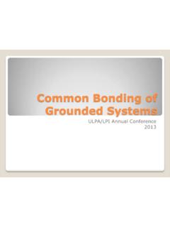
7 A bond is required from the general mass of steelwork to the sensor or transmitter housing either using a flat short braid or a cable of at least 4mm2 cross sectional area. In most instances this bond is automatically made by fixing the metallic transmitter housing to the plant structure. This bond ensures the voltage difference between the signal conductors and the transmitter housing is below the transmitter s insulation rating. Please note that the transmitters or sensors are connected to the Protected Equipment terminals of the SD and not the Field Cables .2-wire transmitter or sensor3-wire transmitter or sensor4-wire transmitter or sensorTO HOST CIRCUITSD PROTECTED FIELD CIRCUIT2-wire transmitters or sensors4-20mA transmitters, conventional and smartWhere the TP48 is not an acceptable solution, either because of Technical suitability or difficulties in mounting, the SD16X, SD32X and SD55X are an excellent transmitters or sensorsVibration Sensors and 4-20mA loop process control systems invariably require three wire connections, when powered from an external may be accomplished in one unit by using the SD32T3 three terminal surge protection Device (SPD).
8 Because the SD32T3 protects all three conductors within the same unit, higher protection is achieved, as the SPD hybrid circuitry is common to all three SD07R3 is available for the protection of 3-wire pressure transducers on low power transmitters or sensorsFlow meters, level detectors, systems such as level detectors require two SDs, one for the supply and the other for the transmitter output. Generally the voltages across the pairs are similar and so the recommended choice would be a pair of SD16X, SD32X or SD55Xs. However, mains powered transmitters should be protected with an SD150X or 275X (depending upon supply voltage) for the supply are catered for by MTL surge Technologies LC30 which is suitable for both 4- and 6-wire load SD rangeJune systems protectionHigh speed data links between buildings or one part of a plant to another have become more common with the widespread use of smart transmitters and the increase in unmanned installations.
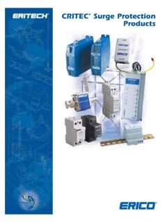
9 The SD range has an SPD suitable for all process I/O applications with a choice of low resistance units, high bandwidth and a variety of voltage variants. The SDR range has been specially designed to meet the requirements for high speed data links with an extremely high PROTECTEDFIELD CIRCUITSD PROTECTED HOST CIRCUITRS232, RS422, RS485SD PROTECTED HOST CIRCUITPROTECTED FIELD CIRCUITBus powered systemsCommunication systemsRS232, RS422, RS485 The recommended choice for these applications is the SD16R or SD32R depending on the maximum driver powered systemsThere are a variety of bus powered systems specially designed for the process industry. The ideal surge protection device for these systems is the SD32R as it has a very high bandwidth and a modest in-line ApplicationsTable 1 shows suitable SD devices for different applications. In some applications alternative devices may be used, for example, where lower in-line resistance or a higher voltage power supply is surge Technologies has operationally tested the recommended SD range with representative highways listed but no formal approval for their use in systems by the respective bodies has been SPDA lternativeAllen Bradley data Highway PlusSD16 RHARTSD32 XSD32, SD32 RHoneywell DESD32 XSD32, SD32 RLonWorks FFT-10 LPT-10 TP-78 IS78 SD32 RSD55 RSD07 RSD32 RModbus & Modbus Plus (RS485)SD16 RPROFIBUS DPSD07 RSD16 RRS232SD16SD16 XRS422SD07 RRS423SD07 RRS485SD07 RTable 1 MTL SD rangeJune power rating for each of these is dependent on the table shown = 1W ( 30 C to +75 C)Pi = ( 30 C to +60 C)Pi = ( 30 C to +40 C)
10 The SD** range is classified as simple apparatus and are intended for use in Zone 2 or safe areas only, because their fuses are not fully SDs should be mounted on the field wiring side to ensure that any surges entering from the field do not damage any intrinsically safe barriers or galvanic isolators in the system. The SDs and IS interfaces should be mounted close to each other but on separate DIN rails in order to maintain the required 50mm clearance between safe area and hazardous area recommended earthing for field mounted devices has been illustrated pre-viously but it is the earthing at the control panel that is more critical as there are usually a number of earthing systems, each with their own requirements. The earthing system illustrated here replaces the instrument 0V bond, the control system PSU bond and the IS earth with one single earth connection to meet all the design requirements and give the most effective protection against the effects of lightning induced area applicationsZone 0/Zone 1 The dangers from lightning induced sparking in Zone 0 are considered real enough to require preventative measures.