Transcription of Technical Guide - Insulated Concrete Wall Forming System ...
1 Technical GuideVersion Pre-Finished, Stay-in-PlaceConcrete Wall FormworkNuform Building Technologies Inc. is an innov-ative quality-driven building technologiescompany. Since the introduction of CONFORM (formerly Royal Building SystemsTM) in 1992, theproduct has received global recognition for itsapproach in providing an innovative solution tothe construction a patented polymer-based stay-in-place formwork for Concrete walls . The extrudedcomponents slide and interconnect together tocreate a Concrete formwork. The result is perma-nent, attractive, andpre-finished Concrete wallsthat can be easily constructed in any climate. CONFORM is composed of numerous modularcomponents for 100mm, 150mm and 200mm (4 , 6 and 8 ) Concrete walls that can be assem-bled to suit any wall layout, whether you arebuilding a vehicle wash, an agricultural facility or alarge industrial requires no painting, and resistsultra-violet radiation.
2 The polymer components will notdecay or deteriorate over a lifespan that can bemeasured in decades. Furthermore, CONFORMis highly durable, virtually maintenance free,impervious to weather, and energy manufactured using R3 extrusiontechnology as an environmentally friendly prod-uct. The polymer components contain over 55%recycled content and are recyclable, energy effi-cient,mold and mildew resistant and offers complete design flexibility andan innovative building product that is easy tomaintain, friendly to the environment, and builtto last. Whether you area developer, contractor,architect, engineer, or designeryou can find attrac-tive and cost effective solutions for your nextproject with CONFORM. Copyright 2012 Nuform Building Technologies rights reserved. No part of this publication may be reproduced in any form or by any means without written permission from Nuform Building Technologies other products, names and services are trademarks or registered trademarks of their respective Solutions for a Better Introduction.
3 12. CONFORM Formwork .. Components .. Layout .. Heights .. Wall Openings .. Properties ..73. Concrete walls with CONFORM .. Concrete Mix .. Concrete Placement .. Concrete Takeoff ..104. Code Evaluations andTechnical Publications .. Code Evaluations .. National Building Code of Canada, 2010 .. Ontario Building Code .. Building Code, 2009 (USA) .. International Residential Code .. Florida Building Code .. Third Party Evaluations .. Technical Publications .. Past Evaluations ..175. Product Performance .. Material Performance .. Structural Performance ofConcrete walls with CONFORM .. Fire Performance .. Sustainability of CONFORM .. Energy Performance .. Vapor and Air Barriers .. Water Penetration .. Indoor Air Quality (IAQ) .. Acoustic Performance .. and Weatherability ..266. Specifications ..27 Section 03 11 33 - Polymer Concrete Formwork .. 271 This Technical Guide has been prepared by NuformBuilding Technologies Inc.
4 (NUFORM ) to assistarchitects, engineers, builders and contractors inunderstanding and designing structures using CON-FORM . It is a part of our continuing effort to providecurrent and practical information to users of Technical Guide provides information on the fol-lowing aspects of CONFORM: CONFORM Formwork Concrete walls with CONFORM Code Evaluations Product Performance Product SpecificationsIn addition to the Technical Guide , the followingguides are also available to assist in designing andbuilding your projects using CONFORM: Engineering Guide Construction GuideAlthough every effort has been made to ensure thatall the information provided in the Technical Guide isfactualand that the numerical values are accurateand consistent with current engineering practice,NUFORM does not assume any liability for errors oroversights resulting from the use of information con-tained in this Guide . Anyone making use of theinformation provided in these guides assumes all lia-bility arising from such use.
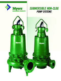
5 1. IntroductionCONFORM uses extruded rigid polymer compo-nents that serve as a pre-finished, stay-in-placeformwork for Concrete walls including bearing walls ,non-bearing walls , shear walls , retaining walls andfoundation walls . The extruded components slideand interconnect together to create a Concrete form-work that remains in place after the Concrete ispoured and cured. CONFORM provides permanent,low maintenance, interior and exterior wall finishes. Four types or thicknesses of CONFORM are avail-able: CF4 (100 mm or 4 ) CF6 (150 mm or 6 ) CF8 (200 mm or 8 ) CF8i (200 mm or 8 , pre- Insulated ). Refer to Table and Figure Components2. CONFORM Formwork(1) The CF8i components are pre- Insulated with 54 mm ( ") of polyurethane insulation. The insulation cavity is on the exterior side of the wall and is pro-tected from the interior with the non-combustible Concrete CONFORMCONFORMC oncrete Wall ThicknessSizeInsulationCF4CF6CF8CF8i(1)1 00 mm(4 )150 mm(6 )200 mm(8 )200 mm(8 )95 mm( )145 mm( )195 mm( )139 mm( )00054 mm( )2 Each type of CONFORM creates a wall formworkusing a variety of components.
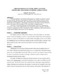
6 The two most com-monly used components, for each wall thickness,are the straight box connector and the panel 232,which are 100 mm (4") and 232 mm (9") components are used for walls of small struc-tures. The various CF4 components are shown inFigure , CF6 and CF8 components are used forbearing and non-bearing walls where no thermalinsulation is required. The various CF6 componentsare shown in Figure , and the various CF8 com-ponents are shown in Figure components are used for Insulated , exterior,bearing and non-bearing walls . The various CF8icomponents are shown in Figure flexibility of the System allows for the combiningof all four types in order to accommodate a wide vari-ety of structures and construction and trim components are available to pro-vide a finishing touch to CONFORM components are available in twostandard colors: tan and whiteCF4CF6CF8CF8iFigure CONFORMFig CF4 ComponentsBox Connector: Straight Box Connector: End Box Connector: CornerBox Connector: 3-way Box Connector: 4-way Box Connector: 45 Panel 93 Panel 182 Panel 232 Spacer 49 Spacer 68 Box JoinerPanel Joiner - Main Panel Joiner - Leg StarterBasic Frame OpeningFig CF6 ComponentsBox Connector: Straight Box Connector: Corner Box Connector: 45 -OutsidePanel 93 Panel 182 Panel 232 Spacer 49 Spacer 68 Box JoinerPanel Joiner - Main StarterBasic Frame Opening3 Fig CF8 ComponentsBox Connector: Straight Box Connector.
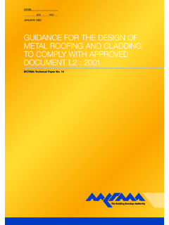
7 Corner Box Connector: 45 -OutsidePanel 93 Panel 182 Panel 232 Spacer 49 Spacer 68 StarterBasic Window FrameFig CF8i ComponentsBox Connector: Straight Box Connector: Corner Box Connector: 45 -OutsideBox Connector: 45 -Inside Panel 93 Panel 182 Panel 232 Spacer 49 Spacer 6845 CONFORM components were developed to suit mm (1'11 8") or 1000 mm (3'3 3 8") grid, asshown in the Figure The mm grid is com-posed of 100 mm (4 ") for the box connector, mm(9 1 8") for the panel P232. It is important to note that the dimension of the panel is composed of mm for theactual panel and a mm joint gap at each side ofthe panels and spacers include a joint gapand thereforethe length of wall created by a panel orspacer is greater than the actual component , panels and spacersare named by compo-nent size and not by the wall length dimension. It isessential to consider the actual wall length createdrather than the component dimension in calculatingthe length of a other components provide for corners, intersec-tions and alternate panel dimensions to suit thelocation of wall intersections, doors, and windows;and the coring is CONFORM components are cored.
8 That is, thewebs of the profiles are punched. This allows the hor-izontal flow of Concrete between the elements. Coresare punched starting from the top of the start of thefirst core is located at 37 mm (11 2")from the top end of the component and the subse-quent cores are mm (3 1 4") apart. For stepped or slopped walls , the components areextruded longer to the nearest increment andfabricated to the exact length required, in order toalign the coring horizontally. Each component is labelled to match the CONFORM components are manufacturedthrough a continuous extrusion process and areprecut to the required lengths for each specific walls that are over 6500 mm (21') high, the indi-vidual boxes and panels are split into two or morelengths. The joints in the boxes and panels are stag-gered near mid height. For pre-assembled wallsections, the staggered joint is typically 1500 mm (5')high and is not less than 900 mm (3'-0").
9 The panelswith the longest length and the boxes with the short-est length are placed at the bottom of the walls . Thehorizontal joints in the CONFORM components donot affect the Concrete pour and Concrete remainsmonolithic. The joints are concealed with an archi-tectural, 'multi-storey', large projects, CONFORM wall sections are usu-ally pre-assembled at the manufacturing facility. Themaximum width of pre-assembled sections is 2233mm (7-4") to suit shipping and handling. TheCONFORM components of a wall section arescrewed together at the webs. For high wall sectionswith staggered joints, the members are screwedtogether on the exterior face, at the staggered LayoutTable Overhead Door OpeningsTable Man Door Openings6 The design flexibility of CONFORMcan accomdatealmost any opening size. Various combinations ofbox connectors, panels and spacer components canaccomodate almost any opening width and the open-ing height can be cut to suit any height.
10 Doors,windows and frames supplied by third parties willwork with CONFORM, as long as the appropriaterough opening size is using all the available components, and specifi-cally the Spacer 49 (50 mm) (2") and Spacer 68 ( ) (2 3 4"), it is possible to achieve most openingsizes within 20 mm (3 4").Where hollow metal doors are installed, the openingmust be specified to accommodate the frame components are selected to suit the width of typ-ical hollow metal frames using a panel with a starterat each jamb. The typical man door openings areshown in Table 6 mm (1 4") bent steel plates are used for over-head door openings, the components are specified tosuit. The typical overhead door openings are shownin Table WidthDoor FrameCONFORM OpeningCONFORMH eader Components3' 0" 915 mm4' 0" 1219 mm6' 0" 1829 mm8' 0" 2438 mm3' 4" 1017 mm4' 4" 1321 mm6' 4" 1931 mm8' 4" 2540 mm3' 4 3 8" 1026 mm4' 4 1 4" 1327 mm6' 4 1 2" 1944 mm8' 4 1 4" 2547 mmBx/P232/Bx/P93/S68/Bx/P232/BxBx/P232/B x/P182/Bx/P182/Bx/P232/BxBx/P232/Bx/P232 /Bx/P182/Bx/P182/Bx/P182/Bx/P232/BxBx/S6 8/P232/Bx/P232/Bx/P232/Bx/P232/Bx/P232/B x/P232/Bx/P232/S49/BxOpening HeightDoor FrameCONFORM OpeningCONFORMH eader Components7' 0" 2134 mm8' 0" 2438 mm7' 2" 2185 mm8' 2" 2489 mm7' 2 1 4" 2191 mm8' 2 1 4" 2496 mmTo suit wall heightTo suit wall heightOpening WidthDoorCONFORM OpeningCONFORMH eader Components10' 0" 3048 mm12' 0" 3658 mm14' 0" 4267 mm16' 0" 4877 mm9' 11 13 16" 3044 mm12' 0 1 8" 3661 mm13' 11 5 8" 4257 mm15' 11 7 8" 4874 mm10 Boxes, 8 Panels 232, 1 Panel 18212 Boxes.