Transcription of Technical guide No. 3 - EMC compliant installation and ...
1 Technical guide No. 3 EMC compliant installation and configuration for a power drive systemABB drives2 EMC compliant installation and configuration for a PDS | Technical guide No. 3 Technical guide No. 3 | EMC compliant installation and configuration for a PDS 3 Copyright 2012 ABB. All rights subject to change without notice. 3 AFE61348280 REV D guide No. 3 EMC compliant installation and configuration for a power drive system4 EMC compliant installation and configuration for a PDS | Technical guide No. 3 Technical guide No. 3 | EMC compliant installation and configuration for a PDS 5 ContentsChapter 1 - Introduction ..7 General ..7 Purpose of this guide ..7 Directives concerning the drive ..7 Who is the manufacturer? ..7 Manufacturer s responsibility ..7 OEM customer as a manufacturer ..8 Panel builder or system integrator as a manufacturer.
2 8 Definitions ..8 Practical installations and systems ..8 Earthing principles ..9 Product-specific manuals ..9 Chapter 2 - Definitions ..10 Electromagnetic compatibility (EMC) of PDS ..10 Immunity ..10 Emission ..10 Power drive system ..11 Types of equipment ..12 Components or sub-assemblies intended for incorporation ..12into an apparatus by the end users ..12 Components or sub-assemblies intended for incorporation ..12into an apparatus by other manufacturers or assemblers ..12 Finished appliance ..13 Finished appliance intended for end users ..13 Finished appliance intended for other manufacturer or assembler ..13 Systems (combination of finished appliances) ..14 Apparatus ..14 Fixed installation ..14 Equipment ..14CE marking for EMC ..14 installation environments ..15 First environment ..15 Second environment.
3 16 EMC emission limits ..16 PDS of category C1 ..16 PDS of category C2 ..16 PDS of category C3 ..16 PDS of category C4 ..17 Chapter 3 - EMC ..19 Solutions for EMC compatibility ..19 Emissions ..196 EMC compliant installation and configuration for a PDS | Technical guide No. 3 Conducted emission ..19 Radiated emission ..20 Enclosure ..20 Cabling and wiring ..20 installation ..21 Clean and dirty side ..21 RFI filtering ..22 Selecting the RFI filter ..23 installation of the RFI filter ..23 Selection of a secondary enclosure ..23 Holes in enclosures ..24360 HF earthing ..25HF earthing with cable glands ..25HF earthing with conductive sleeve ..26360 earthing at motor end ..27 Conductive gaskets with control cables ..28 The shielding should be covered with conductive tape..28 installation of accessories.
4 29 Internal wiring ..29 Control cables and cabling ..31 Power cables ..32 Transfer impedance ..33 Use of ferrite rings ..33 Simple installation ..35 Chapter 4 - Practical examples ..35 Example of by-pass system <100 kVA ..36 Typical example of 12-pulse drive ..37 Example of EMC plan ..39 Chapter 5 - Bibliography ..41 Chapter 6 - Index ..42 Technical guide No. 3 | EMC compliant installation and configuration for a PDS 7 Chapter 1 - IntroductionGeneralThis guide assists design and installation personnel when trying to ensure compliance with the radio frequency requirements of the EMC Directive in the user s systems and installations when using AC drives. The radio frequency range starts from 9 kHz. However, most standards at the moment deal with frequencies that are higher than 150 frequency range below 9 kHz, that is, harmonics, is dealt with Technical guide No.
5 6 guide to harmonics with AC drives .Purpose of this guideThe purpose of this guide is to guide original equipment manufac-turers (OEM), system integrators and panel builders ( assemblers) in designing or installing AC drive products and their auxiliary components into their own installations and systems. The aux-iliaries include contactors, switches, fuses, etc. By following these instructions it is possible to fulfill EMC requirements and give CE marking when concerning the driveThere are three directives that concern variable speed drives. They are the Machinery Directive, Low Voltage Directive and EMC Directive. The requirements and principles of the directives and use of CE marking are described in Technical guide No. 2 EU Council Directives and adjustable electrical power drive systems.
6 This document deals only with the EMC is the manufacturer?According to the EMC Directive (2004/108/EC), the definition of a manufacturer is following: This is the person responsible for the design and construction of an apparatus covered by the Directive with a view to placing it on the EEA market on his own behalf. Whoever modifies substantially an apparatus resulting in an as-new apparatus, with a view to placing it on the EEA market, also becomes the manufacturer. Manufacturer s responsibilityAccording to the EMC Directive the manufacturer is responsible for attaching the CE mark to each unit. Equally the manufacturer is responsible for writing and maintaining Technical documenta-tion (TD).8 EMC compliant installation and configuration for a PDS | Technical guide No. 3 OEM customer as a manufacturerIt is well known that OEM customers sell equipment using their own trademarks or brand labels.
7 Changing the trademark, brand label or the type marking is an example of modification resulting in as new converters sold as OEM products shall be considered components ( complete drive module (CDM) or basic drive module (BDM)). Apparatus is an entity and includes any documentation (manuals) intended for the final customer. Thus, the OEM-cus-tomer has sole and ultimate responsibility concerning the EMC of equipment, and he shall issue a Declaration of Conformity and Technical documentation for the builder or system integrator as a manufacturerAccording to the EMC Directive, a system is defined as a com-bination of several types of equipment, finished products, and/or components combined, designed and/or put together by the same person ( system manufacturer) intended to be placed on the market for distribution as a single functional unit for an end- user and intended to be installed and operated together to perform a specific panel builder or system integrator typically undertakes this kind of work.
8 Thus, the panel builder or system integrator has sole and ultimate responsibility concerning the EMC of the system. He cannot pass this responsibility to a order to help the panel builder/system integrator, ABB Oy offers installation guidelines related to each product as well as general EMC guidelines (this document).DefinitionsThe EMC Product Standard for Power drive Systems, EN 61800-3 (or IEC 61800-3) is used as the main standard for variable speed drives. The terms and definitions defined in the standard are also used in this installations and systemsThis guide gives practical EMC examples and solutions that are not described in product specific manuals. The solutions can be directly used or applied by the OEM or panel guide No. 3 | EMC compliant installation and configuration for a PDS 9 Earthing principlesThe earthing and cabling principles of variable speed drives are described in the manual Grounding and cabling of the drive system , code 3 AFY61201998.
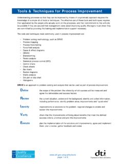
9 It also includes a short descrip-tion of interference manualsDetailed information on the installation and use of products, cable sizes etc. can be found in the product specific manuals. This guide is intended to be used together with product specific EMC compliant installation and configuration for a PDS | Technical guide No. 3 Disturbance levelIndependent variable eg,frequencyImmunity levelImmunity limitEmission limitEmission levelCompatibility marginChapter 2 - Definitions Electromagnetic compatibility (EMC) of PDSEMC stands for Electromagnetic compatibility. It is the ability of electrical/electronic equipment to operate without problems within an electromagnetic environment. Likewise, the equipment must not disturb or interfere with any other product or system within its locality.
10 This is a legal requirement for all equipment taken into service within the European Economic Area ( EEA). The terms used to define compatibility are shown in figure 2-1 Immunity and emission variable speed drives are described as a source of interfer-ence, it is natural that all parts which are in electrical or airborne connection within the power drive system (PDS) are part of the EMC compliance. The concept that a system is as weak as its weakest point is valid equipment should be immune to high-frequency and low-frequency phenomena. High-frequency phenomena include electrostatic discharge (ESD), fast transient burst, radiated elec-tromagnetic field, conducted radio frequency disturbance and electrical surge. Typical low-frequency phenomena are mains voltage harmonics, notches and source of high-frequency emission from frequency converters is the fast switching of power components such as IGBTs and control electronics.