Transcription of Technical Information, Proline Prosonic Flow 93T Portable
1 TI085D/06/ InformationProline Prosonic Flow 93T PortablePortable ultrasonic flow measuring systemVolume flow measurement of liquidsApplicationsThe sensors are perfectly suited for the non-contactmeasurement of pure or slightly contaminated liquids, regardless of the pressure or electrical conductivity. Ideal solution for temporary use everywhere precise measurement or verification is required Particularly suitable for retrofitting, monitoring and verifying measuring points Suitable for pipe diameters from DN 15 to 4000 ( to 160") Suitable for fluid temperatures rangingfrom 40 to +170 C ( 40 to +338 F) Can be used with all metal and plastic pipes lined or unlined and with composite pipes Ideal solution for all applications with sound-conducting liquids, water, wastewater, oils, solvents, acids, hydrocarbons and chemicals Integrated data logger Easy data transfer via USB stick without additional softwareFeatures and benefitsThe Prosonic Flow ultrasonic clamp-on system allows accurate and cost-effective flow measurement from outside the pipe and without the need to interrupt the process.
2 The flow measurement is bidirectional and causes no pressure loss. Easy, safe and menu-guided sensor mounting ensures precise measuring results Easy and safe commissioning via Quick Setup menus Automatic frequency scan for optimized installation and maximum measuring performance Current input for parallel data acquisition or for verifying other devices Remote configuration and measured value display using Endress+Hauser's FieldCare softwareProline Prosonic Flow 93T Portable2 Endress+HauserTable of contentsFunction and system design.. 3 Measuring principle .. 3 Measuring system .. 3 Sensor selection and arrangement .. 5 Input .. 6 Measured variable .. 6 Measuring range .. 6 Operable flow range .. 6 Input signal .. 6 Output .. 6 Output signal .. 6 Low flow cut off .. 6 Galvanic isolation .. 6 Power supply .. 7 Measuring unit electrical connection .. 7 Supply voltage .. 7 Connecting cable (sensor/transmitter) .. 7 Potential equalization .. 7 Performance characteristics.
3 8 Reference operating conditions .. 8 Maximum measured error .. 8 Repeatability .. 9 Operating conditions: installation .. 9 Installation instructions .. 9 Inlet and outlet runs .. 10 Operating conditions: environment .. 11 Ambient temperature range .. 11 Storage temperature .. 11 Degree of protection .. 11 Shock and vibration resistance .. 11 Electromagnetic compatibility (EMC) .. 11 Operating conditions: process .. 12 Medium temperature range .. 12 Medium pressure range (nominal pressure) .. 12 Pressure loss .. 12 Mechanical construction .. 13 Design, dimensions .. 13 Weight .. 18 Materials .. 18 Human interface .. 19 Display elements .. 19 Operating elements .. 19 Language group .. 19 Remote operation .. 19 Certificates and approvals .. 20CE mark .. 20C-Tick mark .. 20 Other standards and guidelines .. 20 Ordering information .. 20 Accessories .. 21 Device-specific accessories .. 21 Measuring principle-specific accessories .. 21 Service-specific accessories.
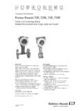
4 22 Documentation .. 23 Registered trademarks .. 23 Proline Prosonic Flow 93T PortableEndress+Hauser3 Function and system designMeasuring principleThe measuring system operates on the principle of transit time difference. In this measurement method, acoustic (ultrasonic) signals are transmitted between two sensors. The signals are sent in both directions, the sensor in question works as both a sound transmitter and a sound the propagation velocity of the waves is less when the waves travel against the direction of flow than along the direction of flow, a transit time difference occurs. This transit time difference is directly proportional to the flow of the transit time difference measurement methodQ = v AaSensorbSensorQVolume flowvFlow velocity (v & t ) tTransit time difference ( t = ta tb)APipe cross-sectional areaThe measuring system calculates the volume flow of the fluid from the measured transit time difference and the pipe cross-sectional area. In addition to measuring the transit time difference, the system simultaneously measures the sound velocity of the fluid.
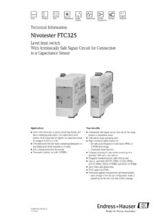
5 This additional measured variable can be used to distinguish different fluids or as a measure of product measuring device can be configured onsite to suit the specific application using Quick Setup systemThe measuring system consists of one transmitter and two transmitter is used both to control the sensors and to prepare, process and evaluate the measuring signals, and to convert the signals to a desired output variable. The sensors work as sound transmitters and sound receivers. Depending on the application and version, the sensors can be arranged for measurement via one or two traverses Prosonic Flow 93T Portable4 Endress+HauserTransmitterSensor/Sensor holdersMounting accessoriesThe requisite mounting distances must be determined for the sensors. information on the fluid, the pipe material used and the exact pipe dimensions is needed to determine these values. The values for the sound velocity of the following fluids, pipe materials and lining materials are stored in the transmitter:If you are using fluids, pipe materials or lining materials other than those listed in the table, and you do not have the corresponding sound velocities for these fluids/materials, you can use the DDU18 and DDU20 sensors to determine the Flow 93T PortableFor mounting in non-hazardous zoneA0011478 Prosonic Flow PProsonic Flow PDN 15 to 65 ( to 2 ")Model 1A0011483DN 15 to 65 ( to 2 ")Model 2A0013504DN 50 to 4000 (2 to 160")A0013475 FluidPipe materialLining Water Sea water Distilled water Ammonia Alcohol Benzene Bromide Ethanol Glycol Kerosene Milk Methanol Toluene Lube oil Diesel Gasoline Carbon steel Cast iron Stainless steel Alloy C PVC PE LDPE HDPE GRP PVDF PA PP PTFE Glass pyrex Cement asbestos Mortar Rubber Tar EpoxyDDU18(sound velocity measurement)DDU20(wall thickness measurement)Nominal diameter range.
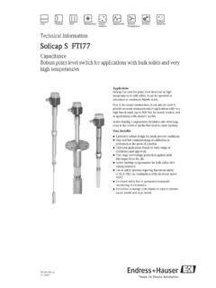
6 DN 50 to 3000 (2 to 120")A0009784 Wall thickness range: Steel pipes: to 50 mm ( to ") Plastic pipes: 4 to 15 mm ( to ")(only suitable for PTFE and PE pipes to a certain extent)A0013478 Proline Prosonic Flow 93T PortableEndress+Hauser5 Sensor selection and arrangementThe sensors can be arranged in two ways: Mounting arrangement for measurement via one traverse:the sensors are located on opposite sides of the pipe. Mounting arrangement for measurement via two traverses:the sensors are located on the same side of the mounting arrangementAMounting arrangement for measurement via one traverseBMounting arrangement for measurement via two traversesThe number of traverses required depends on the sensor type, the nominal diameter and the thickness of the pipe wall. We recommend the following types of mounting:BASensor TypeNominal DiameterSensor FrequencySensor IDType of Mounting 1) Prosonic Flow PDN 15 to 65 ( to 2 ")6 MHzP-CL-6F*2 (or 1) traversesDN 50 to 65 (2 to 2 ")6 MHz (or 2 MHz)P-CL-6F*P-CL-2F*2 (or 1) traverses 2)DN 80 (3")2 MHzP-CL-2F*2 traversesDN 100 to 300 (4 to 12")2 MHz (or 1 MHz)P-CL-2F*P-CL-1F*2 traverses 3)DN 300 to 600 (12 to 24")1 MHz (or 2 MHz)P-CL-1F*P-CL-2F*2 traverses 3)DN 650 to 4000 (26 to 160")1 MHz (or MHz)P-CL-1F*W-CL-05F*1 traverse 3)1) The installation of clamp-on sensors is principally recommended in the 2 traverse type installation.
7 This type of installation allows the easiest and most comfortable type of mounting and means that a system can also be mounted even if the pipe can only be accessed from one side. However, in certain applications a 1 traverse installation may be preferred. These include: Certain plastic pipes with wall thickness > 4 mm ( ") Pipes made of composite materials such as GRP Lined pipes Applications with fluids with high acoustic damping2)If the pipe nominal diameter is small (DN 65 / 2 " and smaller), the sensor spacing with Prosonic Flow P can be too small for two traverse installation using sensor P-CL-2F*. In this case, the 1 traverse type of installation must be ) MHz sensors ( Prosonic Flow W) are also recommended for applications with composite material pipes such as GRP and may be recommended for certain lined pipes, pipes with wall thickness > 10 mm ( "), or applications with media with high acoustic damping. In addition, for these applications we principally recommend mounting the W sensors in a 1 traverse Prosonic Flow 93T Portable6 Endress+HauserInputMeasured variableFlow velocity (transit time difference proportional to flow velocity)Measuring rangeTypically v = 0 to 15 m/s (0 to 50 ft/s) at the specified measuring accuracyOperable flow rangeOver 150 : 1 Input signalCurrent input Galvanically isolated Passive: 0/4 to 20 mA, Ri < 150 , max.
8 30 V DC Terminal voltage: min. 2 V DC to max. 30 V DC Time constant selectable ( to 100 s) Full scale value adjustable Temperature coefficient: typ. % C ( = of reading) Resolution: AOutputOutput signalData logger functionThe device has a data logger function. The measured values can be stored in CSV format on an external USB storage device (FAT 16/FAT 32). A recording cycle of between 1 and 99999 seconds can be selected. USB storage devices with a maximum capacity greater than 2 GB should not be used. Approx. 130 bytes are needed per recording. The standard supplied USB storage device has a maximum capacity of 1 following values are stored: Time ( hh:mm:ss) Flow Sound velocity Flow velocity Signal strength Signal to noise ratio Totalizer (1 to 3) System status 0/4 to 20 mA current input (flow rate and active current value)Each recording is marked with the tag name and device-specific information , such as the serial number for flow cut offSwitch points for low flow cutoff are isolationAll circuits for inputs, outputs, and power supply are galvanically isolated from each Prosonic Flow 93T PortableEndress+Hauser7 Power supplyMeasuring unit electrical connectionA0011480 Connecting the transmitter1ON/OFF switch (press switch 3 seconds)2 Current input connection3 USB plug connection4 Connecting cable connection (CH-DN, downstream)5 Connecting cable connection (CH-UP, upstream)6 FXA193/FXA291 modem connection7 Charger connection (a selection of detachable plug adapters is available)Supply voltageTransmitterPower unit 100 to 240 V AC, 47 to 63 Hz to Power Adapter (12 V DC, A)NiMH accumulator Operating time.
9 At least 8 hours Charge time: approx. hoursSensorPowered by the transmitterConnecting cable (sensor/transmitter)Only use the connecting cables supplied by Endress+ versions of the connecting cables are available 21. Cable material: PTFE Cable lengths: 5 m ( ft), 10 m ( ft)!Note! To ensure correct measuring results, route the connecting cable well clear of electrical machines and switching equalizationFor potential equalization, no special measures are IN12V DCSERVICECH-UPCH-DN1237654 Proline Prosonic Flow 93T Portable8 Endress+HauserPerformance characteristicsReference operating conditions Fluid temperature: +20 to +30 C Ambient temperature: +22 C 2 K Warm-up period: 30 minutes Sensors and transmitter are grounded The measuring sensors are correctly installedMaximum measured errorThe measured error depends on a number of factors. A distinction is made between the measured error of the device ( Prosonic Flow 93T = % of the measured value) and an additional installation-specific measured error (typically % of the measured value) that is independent of the installation-specific measured error depends on the installation conditions on site, such as the nominal diameter, wall thickness, real pipe geometry, fluid, sum of the two measured errors is the measured error at the measuring of the measured error in a pipe with a nominal diameter DN > 200 (8")aMeasured error of the device ( % % )bMeasured error due to installation conditions (typically % )cMeasured error at the measuring point: % % + % = 2 % % Measured error at the measuring pointThe measured error at the measuring point is made up of the measured error of the device ( % ) and the measured error resulting from the installation conditions on site.
10 Given a flow velocity > m/s (1 ft/s) and a Reynolds number > 10 000, the following are typical error diameterDevice error limits+Installation-specific error limits (typical) Error limits at the measuring point (typical)DN 15 ( ") % % + % 3 % % 25 to 200 (1 to 8") % % + % 2 % % > DN 200 (8") % % + % 2 % % = of = of full scale value [ Prosonic P: DN 15 to 65 ( to 2 ") = 10 m/s (33 ft/s), DN 50 to 4000 (2 to 160") = 15 m/s (50 ft/s)] Proline Prosonic Flow 93T PortableEndress+Hauser9 Measurement ReportIf required, the device can be supplied with a factory measurement report. To certify the performance of the device, a measurement is performed under reference conditions. Here, the sensors are mounted on a pipe with a nominal diameter of DN 50 (2") or DN 100 (4") measurement report guarantees the following error limits of the device [at a flow velocity > m/s (1 ft/s) and a Reynolds number > 10 000]:Repeatability % for flow velocities > m/s (1 ft/s)Operating conditions: installationInstallation instructionsMounting locationCorrect flow measurement is possible only if the pipe is full.