Transcription of Technical Information Prosonic S FMU90 - …
1 Technical Information Prosonic S FMU90 . Transmitter in housing for field or top-hat rail mounting for the ultrasonic sensors FDU90/91/91F/92/93/95/96. Application for level measurement Your benefits Continuous, non-contact level measurement of fluids, Simple, menu-guided operation with 6-line plain text pastes, sludge and powdery to coarse bulk materials display; 15 languages selectable with 1 or 2 ultrasonic sensors Envelope curves on the display for quick and simple Measuring range up to 70 m diagnosis (depending on sensor and material measured) Easy operation, diagnosis and measuring point Level limit detection (up to 6 relays) documentation with the supplied "ToF-Tool - Pump control (alternating); rake control FieldTool Package" operating program.
2 Option: additional pump control functions (pump Option: four digital inputs ( for pump feedback). function test, ..) and one external temperature input Calculations: average, difference, sum Time-of-flight correction via integrated or external temperature sensors Application for flow measurement Linearisation (up to 32 points, freely configurable). Flow measurement in open channels and measuring Linearisation tables for the most common flumes and weirs with 1 or 2 ultrasonic sensors weirs pre-programmed and selectable Simultaneous measurement of level and flow in a Online calculation of the flume-/weir-flows via stormwater overflow basin with only 1 sensor integrated flow curves Flow measurement with back water detection (2 Pre-programmed pump control routines sensors) or sludge detection System integration via HART or PROFIBUS DP.
3 Up to 3 totalizers and 3 (resettable) counters; Automatic detection of the sensors FDU9x optionally resettable via digital inputs The sensors of the former series FDU8x can be Counting or time pulse output for control of external connected (for certificates see note on page 8). units TI397F/00/ 71098286. Prosonic S FMU90 . Table of Contents Function and system design.. 3 Climate class .. 21. Measuring principle .. 3 Vibration resistance .. 21. Blocking distance .. 3 Ingress protection .. 21. Time-of-flight correction .. 3 Electromagnetic compatibility (EMC) .. 22. Interference echo suppression .. 3. Pump control .. 3 Mechanical construction .. 23. Linearisation .. 4 Housing versions.
4 23. Special functions .. 4 Dimensions of the field housing .. 23. Datalog functions .. 4 Dimensions of the DIN-rail housing .. 24. Application examples for level measurements .. 5 Dimensions of the separate display and operating module .. 26. Application examples for flow measurements .. 6 Weight .. 26. System integration HART .. 7 Materials .. 26. System integration PROFIBUS DP .. 7. Human interface .. 27. Display and operating module .. 27. Input .. 8. Operating menu .. 27. Sensor inputs .. 8 Basic setup .. 27. External limit switches Locking of the instrument .. 27. (option) .. 8. External temperature sensor .. 8. Certificates and Approvals .. 28. CE mark .. 28. Output .. 9. Ex approval.
5 28. Analogue outputs .. 9 External standards and guidelines .. 28. Relay outputs .. 9. PROFIBUS DP interface .. 10. Ordering Information .. 29. Product structure .. 29. Auxiliary energy .. 10. Scope of delivery .. 29. Supply voltage/. Power consumption/. Current consumption .. 10 Accessories .. 30. Galvanic isolation .. 10 Commubox FXA191 HART .. 30. Fuse .. 10 Commubox FXA195 HART .. 30. Commubox FXA291 .. 30. Protection cover for the field housing .. 30. Electrical connection .. 11. Mounting plate for the field housing .. 30. Terminal compartment of the field housing .. 11 Mounting bracket .. 31. Cable entries of the field housing .. 11 Adaption plate for remote display .. 31. Terminal compartment of the DIN-rail housing.
6 12 Overvoltage protection HAW56x .. 32. Terminal assignment .. 13 Temperature sensor FMT131 .. 36. Terminals .. 15. Connection of the sensors FDU9x .. 16. Synchronization line .. 17 Supplementary documentation .. 37. Connection of the separate display and operating module .. 17 Innovation booklet .. 37. Connection of external switches Technical Information .. 37. (for FMU90 -**B**) .. 18 Operating instructions Connection of a temperature sensor .. 19 (for transmitter FMU90 ) .. 37. Description of Instrument Functions .. 37. Safety Instructions .. 37. Performance characteristics.. 21. Reference operating conditions .. 21. Measuring uncertainty .. 21 .. 38. Typical accuracy .. 21. Measured value resolution.
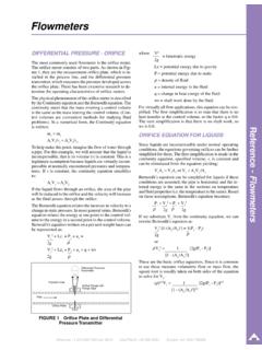
7 21 .. 39. Measuring frequency .. 21. Influence of the vapor pressure .. 21. Ambient conditions .. 21. Ambient temperature .. 21. Storage temperature .. 21. 2 Endress + Hauser Prosonic S FMU90 . Function and system design Measuring principle FDU9x Prosonic S. BD FMU90 . 100%. Prosonic S FDU9x FMU90 . D D. E F. Q. V. L. 0%. L00-FMU90xxx-15-00-08-xx-009. BD: blocking distance; D: distance from sensor membrane to fluid surface; E: empty distance F: span (full distance);. L: level; V: volume (or mass); Q: flow The sensor transmits ultrasonic pulses in the direction of the product surface. There, they are reflected back and received by the sensor. The transmitter Prosonic S measures the time t between pulse transmission and reception.
8 From t (and the velocity of sound c) it calculates the distance D from the sensor membrane to the product surface: D = c t/2. From D results the desired measuring value: level L. volume V. flow Q across measuring weirs or open channels Blocking distance The span F may not extend into the blocking distance BD. Level echos from the blocking distance can not be evaluated due to the transient characteristics of the sensor. The blocking distances of the individual sensors are given in the following documents: TI 396F for the sensors FDU 90/91/91F/92/93/95/96. TI 189F for the sensors FDU 80/80F/81/81F/82/83/84/85/86. Time-of-flight correction In order to compensate for temperature dependent time-of-flight changes, a temperature sensor is integrated in the ultrasonic sensors.
9 Optionally, the Prosonic S FMU90 has an input for an external temperature sensor ( FMU90 -**B**). The following sensor can be connected: Pt100. FMT131 from Endress+Hauser The external sensor mus be used for the heated version of the ulstrasonic sensors FDU90 and FDU91. Interference echo suppression The interference echo suppression feature of the Prosonic S ensures that interference echos ( from edges, welded joints and installations) are not interpreted as a level echo. Pump control individaully configurable for each pump: pump switching delay, to prevent overlaod of the power supply system backlash time and backlash interval, for complete draining of shafts or channels crust reduction at pump shaft walls by fine adjustment of the switch point Endress + Hauser 3.
10 Prosonic S FMU90 . Linearisation Pre-programmed linearisation curves Types of vessels horizontal, cylindrical tank spherical tank tank with pyramidal bottom tank with conical bottom tank with flat, inclined bottom Flow curves for flumes and weirs1). Khafagi-Venturi flume ISO-Venturi flume BST2)-Venturi flume Parshall flume Palmer-Bowlus flume Rectangular weir Rectangular constricted weir NFX3) rectangular weir NFX3 rectangular constricted weir Trapezoidal weir V-notch weir BST2 V-notch wier NFX3 V-notch weir The pre-programmed linearisation curves are calculated on-line. Linearisation formula for flow measurements1. Q = C (h + h ). "h" is the upstream level. The parameters , , and C can be freely programmed by the user.