Transcription of Technical Information RoHS - MAMAC Systems, …
1 HUMIDITY TRANSDUCER SPECIFICATIONSA ccuracy*: 2% / 3% RHRange: 0-100% RHHysteresis: 1%Supply Voltage: 12-40 VDC 12-35 VAC (VDC output units only)Compensated Temp Range: -30 F to 130 F (-35 C to 55 C)Load Impedance: 3 K ohms max. at 40 VDC (mA output units) 1K ohms min. (VDC output units)* Includes non-linearilty and non-repeatabilityInspectionRequirementsF or Additional Information See HU-226 Data SheetINSTALLATION8189 Century Boulevard Minneapolis, MN 55317-8002 USA800-843-5116 952-556-4900 Fax HU-226 Technical / HUMIDITY TRANSDUCERI nspect the package for damage.
2 If damaged, notify the appropriate carrier immediately. If undamaged, open the package and inspect the device for obvious damage. Return damaged products. Do not use on oxygen service, in an explosive/hazardousenvironment, or with flammable/combustible media. Disconnect power supply before installation to prevent electrical shock and equipment damage. Make all connections in accordance with the job wiring diagram and in accordance with national and local electrical codes. Use copper conductors only. Use electrostatic discharge precautions ( , use of wrist straps) during installation and wiring to prevent equipment damage.
3 Avoid locations where severe shock or vibration, excessive moisture or corrosive fumes are present. NEMA Type 4 housings are int ended for outdoor use primarily to provide a degree of protection against wind-blown dust, rain, and hose-directed water. Do not exceed ratings of the device. Tools (not provided)- Digital Volt-ohm Meter (DVM)- Appropriate screwdriver for mounting screws- Appropriate drill and drill bit for mounting screws Appropriate accessories Two #8 self-tapping mounting screws (not provided) Training: Installer must be a qualified, experienced technicianRoHSHU-226 Duct MountTHERMISTOR SENSOR SPECIFICATIONSI nterchangeability: CHeat Dissipation: mW/ CR/T Characteristi cs: Refer to (See Temperature Sensor section)Operating Temp Range.
4 -30 F to 130 F (-35 C to 55 C)Conformance: EMC Standards EN50082-1(1992) EN55014(1993)/EN60730-1(1992)PLATINUM RTD SENSOR SPECIFICATIONSA ccuracy: at 0 CResistance: 100 or 1,000 ohm at 0 CStandard: DIN 43760 Heat Dissipation: mW/ CR/T Characteristi cs: Refer to (See Temperature Sensor section)Conformance: EMC Standards EN50082-1(1992) EN55014(1993)/EN60730-1(1992)GENERAL SPECIFICATIONSE nvironmental: 10-90%RH Non-CondensingEnclosure: 18 Ga Steel NEMA 4 (IP-65)Finish: Baked on enamel - PMS2GR88 BTermination: Unpluggable screw terminal blockWire Size: 12 Ga maximumWeight: Duct Mount: lbs.
5 (.45 kg) TEMP SENSORACCURACY(4-20 mA 2-wire)(0-5 VDC/0-10 VDC field selectable)mAVDCEx: HU-226-2-mA-3 - Temp/Humidity Transducer, 2%RH accuracy with 4-20 mA output and 1,000-ohm Platinum Resistance vs. Temperature Tables,please refer to OUTPUT 2%ORDERING Information - HU-226- 3% 1 2 3 4 5 7 81012131415171821100 ohm Platinum RTD1,000 ohm Nickel RTD (5,000 PPM)1,000 ohm Plat inum RTD 1,000 ohm Nickel RTD (6,000 PPM)1,000 ohm Balco RTD10,000 ohm NTC Thermistor (Type III)10,000 ohm NTC Thermistor (Carel)3,000 ohm NTC Thermistor10,000 ohm NTC Thermistor (Type II)
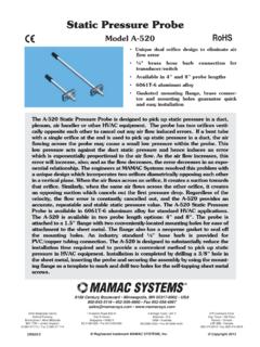
6 5,000 ohm NTC Thermistor1,035 ohm Silicon PTC100,000 ohm NTC Thermistor20,000 ohm NTC Thermistor2,252 ohm NTC Thermistor1,800 ohm NTC ThermistorOperating Temp Range: -30 F to 130 F (-35 C to 55 C)Warning:Caution:Model HU-226 Technical / HUMIDITY TRANSDUCERPage 2 of 4 TYPICAL APPLICATIONS (wiring diagrams)HU-226 humidity transducers are 4-20 mA output units powered with a 12-40 VDC following describes the proper wiring of these humidity and temp sensors with mA output:HUMIDITY SENSOR:1. Remove the terminal block by carefully pulling it off the circuit Locate the [+] and [-] terminal markings on the Attach the supply voltage to the [+] Connect the 4-20 mA output ([-] terminal)
7 To the controller s input Ensure that the power supply common is attached to the common bus of the Re-insert the terminal block to the circuit board and apply power to the Check for the appropriate output signal using a DVM set on DC milliamps connected in series with the [-] Signal+Common++Shield/GroundController / Meter / RecordermA Output Transducer Only12-40 VDC Power Supply+Controller / Meter / RecordermA Output Transducer OnlyFigures 1 & 2 illustrate typical wiring diagrams for the HU-226, 4-20 mA, two-wire humidity 1 - Wiring for mA Output Humidity Transducer with External DC Power SupplyFigure 2 - Wiring for mA Output HumidityTransducer where Controller or Meter has Internal DC Power SupplyRoHSMountingHU-226 (DUCT)
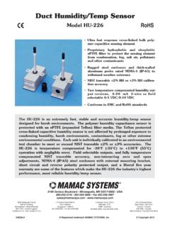
8 - Refer to Figure 6 for mounting Drill 5/8 hole in appropriate Mount transducer on a vertical surface with two #8 self-tapping screws (not provided).3. Pull wires through knockout and make necessary connec-tions (see wiring diagrams).4. Replace cover and tighten Philips maximum 12 AWG wire for wiring terminals. Refer to Figures 1, 2, 3, & 4 for wiring Information and Figure 5 for dip switch HU-226 Units with mA OutputHU-226 Humidity Transducer with mA OutputCaution: If you are using grounded AC, the hot wire must be on the [+] terminal.
9 Also, if you are using a controller without built-in isolation, use an isolation transformer to supply the HU-226 : This product contains a half-wave rectifier power supply and must not be powered off transformers used to power other devices utilizing non-isolated full-wave rectifier power supplies. Caution: When multiple units are powered from the same transformer, damage will result unless all 24G power leads are connected to the same power lead on all devices. It is manda-tory that correct phasing be maintained when powering more than one device from a single transformer.
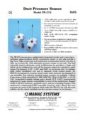
10 MA OutputTEMP SENSOR:1. Remove the terminal block by carefully pulling it off the circuit Use shielded 18-22 AWG wire to connect temp sensor as shown in Figures 1 & Signal+CommonShield/GroundTempInputModel HU-226 Technical / HUMIDITY TRANSDUCERPage 3 of 4 RoHSTYPICAL APPLICATIONS (wiring diagrams)NeutralHot+Controller / Meter / RecorderVDC Output Transducer Only12-35 VAC TransformerFigures 3 & 4 illustrate typical wiring diagrams for the HU-226, 0-5/0-10 VDC output humidity 3 - Wiring for VDC Output when applied with External AC SupplyFigure 4 - Wiring for VDC Output when applied with External DC Power SupplySignal+CommonSupplyO+Controller / Meter / RecorderVDC Output Transducer Only12-40 VDC TransformerInput SignalCommonHU-226 humidity transducers with VDC output are field selectable 0-5 VDC or 0-10 VDC output and can be powered with either 12-40 VDC or 12-35 following describes the proper wiring of these humidity transducers with VDC output.