Transcription of Technical Manual 1 Design of Monopole Bases
1 Technical Manual 1 Design of Monopole Bases By Daniel Horn, Copyright 2011 by Tower Numerics Inc. All rights reserved. Care has been taken to ensure that the material found in this publication is both useful and accurate. However, please be aware that errors may exist in this publication, and that Tower Numerics Inc. makes no guarantees concerning accuracy of the information found here or in the use to which it may be put. Contents Introduction 1 Historical AISC Method For Building Flexible Base Example Stiff Plate Example Example Grouted Base Plates 19 Process Equipment Design Example Lutz Example Complete Square Base Plate Load On Modification for Clipped Example Example Complete Square Base Plate Load Example Complete Circular Base Plate Method.
2 54 Example Ungrouted Base Plates 63 Determining Bolt Example Example Example Determining Plate Stresses 71 Effective Width Based Upon Plate Process Equipment Example Base Plates With Gussets ..77 Alternate Method Technical Manual 1 Design of Monopole Bases Contents iii Alternate Method Alternate Method Method of Example Alternate Method 1 Square Base Alternate Method 2 Circular Base Boulos Method (New York Dept. of Transportation)..87 Diagonal Loading Parallel Loading Owens Method (New York Dept. of Transportation)..94 ASCE Manual 72 (Proposed 2003 Revision)..95 Example Anchor Bolts 99 Material Example Recommendations 105 Determining Base Plate Grouted Base Ungrouted Base Plates.
3 105 Determining Base Plate Construction Bibliography 108 Glossary of Terms 111 Index 113 iv Contents Technical Manual 1 Design of Monopole Bases Technical Manual 1 Design of Monopole Bases Introduction 1 Introduction Organization The following chapters will cover the following topics: 1. An historical perspective including the AISC approach to base plate Design for building columns. 2. Classical methods for determining bolt forces and concrete stresses for grouted base plates.
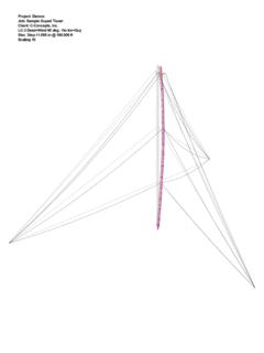
4 3. Classical methods for determining bolt forces for ungrouted base plates. 4. Evaluation of various methods currently being used to determine base plate bending stresses for plain and stiffened plates Technical Manual 1 Design of Monopole Bases Introduction 2 Historical Perspective Monopoles have become increasingly popular for use in the telecommunication industry. The advantages include architectural attractiveness and a minimal use of land. Poles are of two general types, tapered polygonal poles and stepped pipe poles. The tapered polygonal pole shown in Fig. 1-1, is custom manufactured to exact diameters required for the Design .
5 Each section is joined using telescoping lap joints. Fig. 1- 1 Technical Manual 1 Design of Monopole Bases Introduction 3 Pipe poles are made from large diameter pipe sections and joined by external or internal flange connections as shown in Fig. 1-2. Fig. 1- 2 While some poles may be directly buried into the earth, the most common method of attaching the pole to the foundation is with a base plate. Technical Manual 1 Design of Monopole Bases Introduction 4 Base plates can be square with clustered anchor bolts as shown in Fig. 1-3 when overturning moments are relatively light. Fig. 1- 3 The clear space below the leveling nut is not limited by the TIA-222 Standard; however, the ASCE Manual (1) suggests limiting the distance to two bolt diameters.
6 AASHTO(2) limits this distance to one bolt diameter. AASHTO also recommends that the minimum base plate thickness be equal to the bolt diameter. Technical Manual 1 Design of Monopole Bases Introduction 5 Base plates can also be polygonal or circular to accommodate a larger number of bolts. The plate may need to have gusset plates (stiffeners) in order to transfer forces due to axial and bending moment to the pole. A typical example is shown in Fig. 1-4. Fig. 1- 4 Poles have been used in the power transmision field since the 1960 s. Prior to that, poles were used almost exclusively for flags(3,4) and for highway structures(2).
7 In recent years, poles have become popular for both electric transmission towers and for telecommunication structures. There is currently no industry standard for the Design of pole base plates. Some state highway departments (New York) have developed their own methods, but no national standard exists. As such, the designer is left to arrive at appropriate methods based upon classical structural mechanics. While some testing has been done on smaller pole base plates used in highway construction (usually poles between 10 and 20 inches in diameter), no testing has been done on larger diameter pole base plates such as used in the telecommunication industry (poles 36 to 72 inches in diameter).
8 Therefore, such Design techniques may or may not be appropriate. Recent finite element studies(5,6,7) have indicated that current Design practices used by pole manufacturers may be under-designed by 20 to 30%. Technical Manual 1 Design of Monopole Bases Introduction 6 Although Monopole failures are a relatively rare occurrence, a number of recent pole failures (see Fig. 1-5) have increased interest in manufacturer s Design and manufacturing techniques. Fig. 1- 5 The purpose of this report is to make available the various Design techniques currently being used in the industry in the hope that more reliable methods of Design may be developed in the future.
9 To begin, let us examine the traditional methods that have been developed for designing building columns subject to axial loads and moment. Technical Manual 1 Design of Monopole Bases Introduction 7 AISC Method For Building Columns Moment resisting base plates for building columns are covered in neither the AISC Specification nor the Manual of Steel Construction. Engineers must therefore refer to textbooks or Technical papers for Design methods although not all texts cover this topic. Working stress methods for analyzing moment resistant base plate can be found in engineering texts(8,9,10,11,12). DeWolf(13) and Thambiratnam(14) compared methods of designing building columns to test data.
10 The AISC method for designing axially loaded base plates defines the critical section as being at .95 times the depth of the structural members for shapes of rectangular cross-section such as wide flanges and tubes. The critical section for pipe is defined at a location equal to .80 times the diameter of the pipe. Two different approaches have been taken to determine the distribution of forces on the base plate, a flexible plate approach and a stiff plate approach. Technical Manual 1 Design of Monopole Bases Introduction 8 Flexible Base Plate Relatively flexible base plates are incapable of maintaining a linear strain distribution and the assumption is made that the compression force is centered beneath the compression flange of the column.