Transcription of Technical Product Guide
1 Introduction .. 1 Theory of Operation .. 3 System Configuration .. 11 Product Specifications .. 17 Field Termination 47 Communication Capabilities .. 59 TriStation 1131 Developer s Workbench .. 63 CEM Programming Language Editor .. 67 Sequence of Events (SOE) 69 Part Number Cross-Reference .. 73 Technical Product GuideTricon SystemsPart No. 9791007-013 August 2006 Information in this document is subject to change without notice. Companies, names and data used in examples herein are fictitious unless otherwise noted. No part of this document may be reproduced or transmitted in any form or by any means, electronic or mechanical, for any purpose, without the express written permission of Triconex. 2006 Invensys Systems, Inc. All Rights , Tricon, Trident, TriStation 1131, and CEMPLE are trademarks of Invensys plc, its subsidiaries and affiliates. All other brands may be trademarks of their respective of the variety of uses for this equipment and because of the differences between this fault-tolerant equipment and traditional programmable logic and process controllers, the user of, and those responsible for applying, this equipment must satisfy themselves as to the acceptability of each application and the use of the illustrations, charts and layout examples shown in this manual are intended solely to illustrate the text of this manual.
2 Because of the many variables and requirements associated with any particular installation, Invensys Systems, Inc. cannot assume responsibility or liability for actual use based upon the illustrative uses and no event will Invensys Systems, Inc. be responsible or liable for indirect or consequential damages resulting from the use or application of this SYSTEMS, INC. DISCLAIMS ANY IMPLIED WARRANTY OF FITNESS FOR A PARTICULAR Systems, Inc. reserves the right to make changes at any time in order to improve design and to supply the most reliable Product . No patent or copyright liability is assumed by Invensys Systems, Inc. with respect to use of information, circuits, equipment or software described in this SUPPORTC ustomers in the and Canada can obtain Technical support from the Customer Satisfaction Center (CSC) at the numbers below. International customers should contact their regional support : T oll-free number 866-746-6477 Toll number508-549-2424 (outside )Fax:Toll Tricon is a fault-tolerant controller based on a Triple-Modular Redundant (TMR) is Fault-Tolerant Control?
3 A fault-tolerant control system identi-fies and compensates for failed control system elements and allows repair while continuing an assigned task without process interruption. A high-integrity control system such as the Tricon is used in critical process appli-cations that require a significant degree of safety and is the Tricon?The Tricon is a state-of-the art controller that provides fault tolerance by means of Triple-Modular Redundant (TMR) architecture. TMR integrates three isolated, parallel control systems and extensive diagnostics in one control system. The system uses two-out-of-three voting to provide high-integrity, error-free, uninterrupted process opera-tion with no single point of Tricon controller uses three iden-tical channels. Each channel indepen-dently executes the control program in parallel with the other two channels. Specialized hardware/software voting mechanisms qualify and verify all digital inputs and outputs from the field, while analog inputs are subject to a mid-value selection each channel is isolated from the others, no single-point failure in any channel can pass to another.
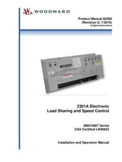
4 If a hard-ware failure does occur on one channel, the other channels override it. Mean-while the faulting module can easily be removed and replaced while the controller is online without interrupting the process. Setting up control programs is simpli-fied with the triplicated Tricon system, because it operates as a single control system from the user s point of view. The user terminates sensors and actua-tors at a single wiring terminal and programs the Tricon with one set of control program logic. The Tricon controller manages the rest!Extensive diagnostics on each channel, module, and functional circuit immedi-ately detect and report operational faults by means of indicators or alarms. The Tricon Fault-Tolerant Controller2 IntroductionAll diagnostic fault information is accessible by the control program and the operator. The program or the oper-ator can use diagnostic data to modify control actions or direct maintenance key features of the Tricon controller that ensure the highest possible system integrity are: No single point of failure Ability to operate with 3, 2 or 1 Main Processor before shutdown Fully implemented and transparent triplication Comprehensive system diagnostics Complete range of I/O modules Dual and single I/O modules for safety-critical points with a limited need for availability Remote I/O up to miles (12 kilometers) away from MPs Simple, online module repair Unsurpassed reliability and availabilityWhat are Typical User Applications?
5 Each day the Tricon supplies increased safety, reliability and availability to a worldwide installed base. The following are a few typical applica-tions. For more information on how a Tricon controller can add value to your applications, ask your sales representa-tive for additional documentation and customer Safety Shutdown (ESD)The Tricon provides continuous protec-tion for safety-critical units in refin-eries, petrochemical/chemical plants and other industrial processes. For example, in reactor and compressor units, plant trip signals for pressure, Product feed rates, expander pressure equalization and temperature are monitored and shutdown actions taken if an upset condition occurs. Traditional shutdown systems implemented with mechanical or electronic relays provide shutdown protection but can also cause dangerous nuisance Tricon increases system integrity, providing automatic detection and veri-fication of field sensor integrity, inte-grated shutdown and control functionality, and direct connection to the supervisory data highway for continuous monitoring of safety-crit-ical Flame SafetyProcess steam boilers function as a crit-ical component in most refinery appli-cations.
6 Protection of the boiler from upset conditions, safety interlock for normal startup and shutdown, and flame-safety applications are combined by one integrated Tricon system. In traditional applications, these functions had to be provided by separate, non-integrated components. But with the fault-tolerant, fail-safe Tricon controller, the boiler operations staff can use a critical resource more produc-tively while maintaining safety at or above the level of electromechanical protection Control SystemsThe control and protection of gas or steam turbines requires high integrity as well as safety. The continuous oper-ation of the fault-tolerant Tricon controller provides the turbine operator with maximum availability while main-taining equivalent levels of safety. Speed control as well as start-up and shutdown sequencing are implemented in a single integrated system. Unsched-uled outages are avoided by using hot-spares for the I/O modules. If a fault occurs in a module, a replacement module is automatically activated without operator Fire and Gas ProtectionThe protection of offshore platforms from fire and gas threats requires continuous availability as well as reli-ability.
7 The Tricon provides this avail-ability through online replacement of faulty modules. Faults in individual modules, field wiring and sensors are managed automatically by built-in diagnostics. Analog fire and gas detec-tors are connected directly to the Tricon, eliminating the need for trip amps. An operator interface monitors fire and gas systems as well as diagnos-tics for the Tricon controller and its attached sensors. Traditional fire and gas panels can be replaced with a single integrated system, saving costly floor space while maintaining high levels of safety and is TriStation?TriStation 1131 Developer's Work-bench is an integrated tool for devel-oping, testing and documenting control programs that execute in the Tricon controller. TriStation 1131 complies with the IEC 61131 International Stan-dard for Programmable Controllers and follows the Microsoft Windows Guide -lines for graphical user about Communication Capabilities?Optional modules enable the Tricon to communicate with other Triconex controllers and with other hosts such as: Modbus masters and slaves Distributed Control Systems (DCS) Operator workstations Host computers using Ethernet ( ) protocolFor more information, see Communi-cation Capabilities on page Tricon is designed with a fully triplicated architecture throughout, from the input modules through the main processors (MPs) to the output of OperationFault tolerance in the Tricon is achieved by means of a Triple-Modular Redun-dant (TMR) architecture.
8 The Tricon provides error-free, uninterrupted control in the presence of either hard failures of components, or transient faults from internal or external Tricon is designed with a fully trip-licated architecture throughout, from the input modules through the main processors to the output modules. Every I/O module houses the circuitry for three independent channels, which are also referred to as legs. Each channel on the input modules reads the process data and passes that information to its respective main processor. The three main processors communicate with each other using a proprietary high-speed bus system called the per scan, the three main processors synchronize and commu-nicate with their two neighbors over the TriBus. The Tricon votes digital input data, compares output data, and sends copies of analog input data to each main main processors execute the control program and send outputs generated by the control program to the output modules. The output data is voted on the output modules as close to the field as possible, which enables the Tricon to detect and compensate for any errors that might occur between the voting and the final output driven to the field.
9 For each I/O module, the system can support an optional hot-spare module which takes control if a fault is detected on the primary module during opera-tion. The hot-spare position can also be used for online system repairs. Main Processor ModulesA Tricon system contains three main processor (MP) modules to control three separate channels of the system. Each main processor operates in parallel with the other two main proces-sors, as a member of a dedicated I/O and COMM processor on each main processor manages the data exchanged between the main processors and the I/O modules. A trip-licated I/O bus is located on the chassis backplane and is extended from chassis to chassis by means of I/O bus each input module is polled, the new input data is transmitted to the main processor over the appropriate channel of the I/O bus. The input data from each input module is assembled into a table in the main processor and stored in memory for use in the hardware voting individual input table in each main processor is transferred to its neigh-boring main processors over the propri-etary TriBus.
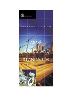
10 During this transfer, hardware voting takes place. The TriBus uses a direct memory access (DMA) programmable device to synchronize, transmit, vote and compare data among the three main a disagreement is discovered, the signal value found in two out of three tables prevails, and the third table is corrected accordingly. One-time differ-ences which result from sample timing variations can be distinguished from a pattern of differing data. The three independent main processors each maintain data about necessary correc-tions in local memory. Any disparity is flagged and used at the end of the scan by the built-in Fault Analyzer routines to determine whether a fault exists on a particular Leg AInput Leg BInput Leg COutput Leg AOutput Leg BOutput Leg CMain Processor CMain Processor BI/O BusI/O BusI/O BusTr iBusTriBu sTr i BusVo t e rMain Processor AInput TerminationOutput TerminationAuto SpareAuto SpareSimplified Tricon Architecture4 Theory of OperationAfter the TriBus transfer and input data voting have corrected the input values, these corrected values are used by the main processors as input to the user-written control program.