Transcription of TECHNICAL SERVICE GUIDE - ApplianceAssistant.com
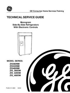
1 GgPUB # 31-909103/02 MODEL SERIES: TECHNICAL SERVICE GUIDEGE Consumer Home services TrainingMonogramSide-By-Side RefrigeratorsWith Electronic ControlsZIS360 NMZIS420 NMZIS480 NMZIS_360 DMZIS_420 DMZIS_480 DMGEA01265 IMPORTANT SAFETY NOTICEThe information in this SERVICE GUIDE is intended for use byindividuals possessing adequate backgrounds of electrical,electronic, and mechanical experience. Any attempt to repair amajor appliance may result in personal injury and propertydamage. The manufacturer or seller cannot be responsible for theinterpretation of this information, nor can it assume any liability inconnection with its avoid personal injury, disconnect power before servicing thisproduct. If electrical power is required for diagnosis or testpurposes, disconnect the power immediately after performing thenecessary ALL GROUNDING DEVICESIf grounding wires, screws, straps, clips, nuts, or washers usedto complete a path to ground are removed for SERVICE , they mustbe returned to their original position and properly Consumer Home services TrainingTechnical SERVICE GuideCopyright 2002 All rights reserved.
2 This SERVICE GUIDE may not be reproduced in whole or in partin any form without written permission from the General Electric Company.! 1 TECHNICAL 3 Model 4 Rating Plate .. 4 Mini-Manual .. 4 Serial Number ..5 Component Locator 9 Machine Compartment .. 9 Door Closure Mechanism .. 10 Doors and Hinges .. 10 Door 11 Rollers and Leveling .. 11 Ice and Water 12 Controls .. 12 Water Valve and Water Tank .. 14 Damper .. 14 Evaporator Fan .. 15 Condenser Fan .. 19 Defrost 20 Adaptive 20 Normal Operating Characteristics .. 21 Abnormal Operating Characteristics .. 21 Liner Protection Mode .. 21 Defrost Heater ..22 Evaporator Thermistor .. 23 Defrost Overtemperature Thermodisk .. 23 Control 24 Touch Panel and Temperature Control Board .. 24 Main Control Board .. 25 Main Control Board Locator Tables .. 31 Climate Control 32 Strip Circuit.
3 32 Component Locator View .. 33 Operation .. 34 Temperature Table .. 35 Climate Control Drawer Top Panel (Mullion) .. 36 Control Board and Display .. 36 Fan and Fan Housing .. 39 Heater .. 40 Airflow .. 42 Table of Contents 2 Table of Contents (cont.)Compartment 44FF/FZ Compartment Lights Diagnostic .. 44 Door Switches .. 45 Master Light Switch (Sabbath Switch) .. 45 Temperature Overload Device (TOD) .. 45 Circuit Breakers .. 46 Light Bulb Replacement .. 49 Refrigeration 50 Condenser Loop .. 51 Refrigerant Charge .. 51 Diagnostic 52 Diagnostic 53 Fresh Food Warm - Freezer Normal .. 53 Fresh Food Too Cold - Freezer Normal .. 54 Fresh Food Warm - Freezer Warm .. 55 Freezer Warm - Fresh Food Normal .. 56 Compressor Not 57 Refrigerator Dead - No Sound, No Cooling .. 58 Damper Door Does Not Operate .. 59 Heavy Frost on Evaporator.
4 60 Evaporator Fan Not Running .. 61 Condenser Fan Not Running .. 3 TECHNICAL Data**For model ZIS 36: WR55X10166. Model ZIS 36D: WR55X10165. Model ZIS 42:WR55X10164. Model ZIS 42D: WR55X10163. Model ZIS 48: ZIS 48D: : Disconnect power cord : Reconnect all grounding parts of this appliance capable of conductingelectrical current are grounded. If grounding wires,screws, straps, clips, nuts, or washers used tocomplete a path to ground are removed forservice, they must be returned to their originalpositions and properly : To avoid personal injury when servicingthe condensing unit, stand on a ladder which willgive enough support to allow removal of the toppanel and safely allow access to SERVICE the Defrost ControlW/No Door Openings ..60 hrs @ 35 minEvap Overtemperature Thermodisc ..60 F-45 FLight Thermostat ..140 F-90 FElectrical Rating: 115 VAC 60 ampMaximum Current mAMaximum Ground Path Resistance.
5 OhmsEnergy Consumption (HUMID) .. *CONTROL POSITION 37-0 F andAMBIENT TEMPERATURE OF 70 F 90 FFresh Food, F .. 36 46 .. 37 48 Frozen Food, F .. (-6) 6 .. (-4) 3 Percent Running 41 46 .. 53 55To access the low-pressure side of the system,install a WR86X0097 valve only on the processtube extending from the compressor Safety Notice:This information is intended for use by individualspossessing adequate backgrounds of electrical,electronic, and mechanical experience. Any attemptto repair a major appliance may result in personalinjury and property damage. The manufacturer orseller cannot be responsible for the interpretationof this information, nor can it assume any liability inconnection with its SYSTEMC ompressor ..983 Btu/hrMinimum Compressor CapacityVacuum .. 26 inchesMinimum Equalized Pressure@ 70 72 PSIG@ 90 PSIGR efrigerant Charge (R134a).
6 OzELECTRICAL SPECIFICATIONSNO LOAD PERFORMANCEREFRIGERATION DIAGNOSISHMI Temperature **Relay ..WR07X10031 Overload .. WR08X10015 Run Capacitor (15 uF) .. WR62X0080 Overtemperature Thermodisc Light .. WR50X10035 Overtemperature Thermodisc Evaporator .. WR50X10036 Defrost Heater .. WR51X10065 Drain Trough ASM .. WR17X11194 Condenser Fan Motor .. WR60X10083 Condenser Fan Blade .. WR60X10049 Evaporator Fan Motor .. WR60X10043 Evaporator Fan Blade .. WR60X10050 Main Board .. WR55X10167 Thermistors (2-FF, 1-FZ, 1-EV) .. WR55X10025 Damper Assembly Fresh Food .. WR60X10085 Evaporator .. WR84X10038 Compressor .. WR84X10037 Filter Dryer .. WR86X0096*For Models ZIS 36 & ZIS 36D: kWh/mo. Models ZIS 42 & ZIS 42 kWh/mo. Model ZIS 48: kWh/mo. Model ZIS 48D: PARTSC ompressorProcessTubeHigh Pressure(Do NOT use)EvaporatorHeat ExchangerCondenserSuctionTubeCondenserLo opDryerOverloadTo CabinetWiringWhiteOrangeBlackRunCapacito rGreen(Ground)To CabinetWiringWhiteBlackOverloadGreen(Gro und)Run CapacitorOrange 4 Rating PlateThe rating plate, located behind the grille panel atthe top of the refrigerator on the right side of theevaporator box, contains the model and serialnumbers.
7 Additionally, the rating plate specifiesthe minimum installation clearances, electricalvoltage, frequency, maximum amperage rating,refrigerant charge, and mini-manual is located behind the grillepanel at the top of the refrigerator. When done,return the mini-manual to its original location forfuture Z - MonogramStyleI - Built-InConfigurationS - Side by SideColorS - Stainless B - Black W - WhiteBlank - Trim ModelSize480 - 48 Inches WideEngineeringA - Initial DesignB - 1st RevisionC - 2nd RevisionD - 3rd TypeF - FlatR - RightL - Left Door SwingIcemaker/ExteriorN - NondispenserModel YearL - 2002 Pre-EnergyM - 2002 EnergyZISS480 NMALHM odel NomenclatureMini-Manual andRating Plate 5 Serial NumberThe serial number consists of two letters, followed by six numerals. The two prefix letters of theserial number indicate the month and year the product was manufactured.
8 The year of manu-facture does not correspond with the model year of the model 6 Component Locator ViewsFigure 1 - Machine CompartmentFigure 2 - Evaporator (Top of Freezer)Condenser FanCompressorDryerMaster Light Switch(Sabbath Switch)Overload &PTCR RelayEvaporatorEvaporatorThermistorEvapo ratorOvertemperatureThermodisc (TOD)Defrost Heater 7 Figure 3 - Water Valve and Capacitor(Center of Machine Compartment)Figure 4 - Evaporator FanFigure 5 - Light Circuit TransformersCapacitorWater ValveEvaporator Fan MotorEvaporator FanConnectorCircuit BreakersDrawer UnderCenter of UnitTransformers 8 Climate ControlDrawer FanFigure 6 - Freezer CompartmentFigure 7 - Fresh Food CompartmentFreezer Door SwitchAuger DriveAirflow GrilleIcemakerCube SolenoidTemperatureOverload Device(TOD)FreezerThermistorFresh FoodDoor SwitchTemperature Touch PadDamperWater FilterFresh FoodThermistorsClimate ControlDrawer DampersTemperatureOverload Device(TOD)LowerFresh FoodLights 9 The outer case is made of prepainted galvanizedsteel.
9 The fresh food and freezer liners arepainted metal with a smooth finish. The liners arenot removable or CompartmentThe machine compartment is located on the top ofthe unit and has a movable chassis that can beextended from the front of the unit to provideaccess to the refrigeration system : Avoid kinking the refrigeration lines whensliding the chassis out and back extend the chassis:1. Remove the grille panel by removing 2 screwsfrom each side (see photo).2. Remove the wire guard and rocker Remove the condenser Loosen 2 (7/16-in.) track bolts from the front ofthe chassis Remove 2 (7/16-in.) rear track bolts and thespacers under the rear of the chassis Pull the chassis forward until it reaches thestops in the tracks, working the refrigerationtubing as you pull the chassis When sliding the chassis back into position, becertain the lines and wiring have not fallenbehind the chassis.
10 Use the grille screws for adjustment whenrealigning the Master Light Switch (Sabbath switch) islocated behind the grille CompartmentChassisRear Track BoltsRear Track BoltsFront Track BoltsFront Track Bolts2 ScrewsCondenserBaffle 10 Doors and HingesThe doors are of one-piece construction with inner door panel and outer door panel cannotbe separated and must be replaced as AdjustmentBe sure the top hinge does not hit the cabinet the door up or down by turning the threadedhinge pin on the bottom hinge of the fresh upper hinge on the freezer door is slotted toallow the freezer door to be adjusted left or RemovalWARNING: Use the appropriate safety equipmentand lifting techniques. Two persons may berequired for door : Use wood or a heavy plastic sheet toprotect the floor where the door will be Remove all food and bins from the inner doorliner and tape door to Disconnect the spring from the pin and theactuator Remove the Allen head bolt, bushing, andspacer from the door and actuator If removing the freezer door, shut off the watersupply, and disconnect the water line andelectrical Remove the upper Lift door up and out to Door HingeNote: If replacing lower door hinge, note theplacement of the door stop (pin).

