Transcription of TECHNICAL SERVICE MANUAL - Viking
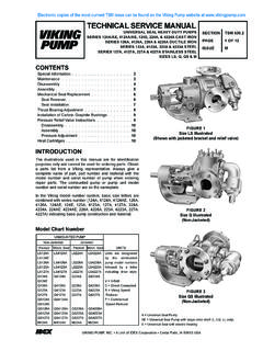
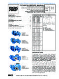
1 Viking PUMP, INC. A Unit of IDEX Corporation Cedar Falls, IA 50613 USASECTIONTSMPAGEISSUE6108 HCONTENTSI ntroduction ..1 Special Information ..2 Lubrication ..2 Installation ..3 Operation ..3 Disassembly ..3 Assembly A Reducer ..4 B Reducer ..5 C Reducer ..6 TECHNICAL Data ..7 Warranty ..8 INTRODUCTIONThe illustrations used in this MANUAL are for identification purposes only and cannot be used for ordering parts. Obtain a parts list from the factory or a Viking representative. Always give the complete name of the repair part and part number along with the reducer part number when ordering repair parts.
2 The reducer part number is stamped on the PUMP AND UNIT MODEL NUMBERSFIGURE 1 A SIZE HELICAL GEAR REDUCER A , B AND C SIZE REDUCERSSIZEPART :1 FIGURE 2 B SIZE HELICAL GEAR REDUCERFIGURE 3 C SIZE HELICAL GEAR REDUCERE lectronic copies of the most current TSM issue can be found on the Viking Pump website at SERVICE MANUAL Viking HELICAL GEAR REDUCERS A , B , AND C SIZESFIGURE 4 TYPICAL INSTALLATIONNOTE: UNIT FURNISHED WITH COUPLING GUARDS AS STANDARDSECTION TSM610 ISSUEHPAGE 2OF 8 DANGER !Before opening any Viking pump liquid chamber (pumping chamber, reservoir, relief valve adjusting cap fitting etc.)
3 , or drive equipment be sure:1. That any pressure in the chamber has been completely vented through the suction or discharge lines or other appropriate openings or That the driving means (motor, turbine, engine, etc.) has been locked out or made non- operational so that it cannot be started while work is being done on pump. 3. That you know what liquid the pump has been handling or in the reducer and the precautions necessary to safely handle the liquid. Obtain a material safety data sheet (MSDS) for the liquid to be sure these precautions are starting unit or reducer, be sure all drive equipment guards are in to follow above listed precautionary mea-sures may result in serious injury or INFORMATIONLUBRICATIONVIKING GEAR REDUCERS ARE SHIPPED WITHOUT OIL.
4 BEFORE OPERATING THE REDUCER, BE SURE TO ADD THE PROPER AMOUNT AND TYPE OF LUBRICANT. CAUTION! DO NOT OVER FILL. See chart SIZEQUANTITYMOTOR OIL TYPE & SERVICEA3/8 PT. (6 OZ.)Use SAE 30 Above 32 FUse SAE 10W Below 32 F B1/2 PT. (8 OZ.)C2 & 1/4 PT. (36 OZ.)1. Remove the breather and add the proper lubricant for the type of SERVICE and quantity given after each size After the first 100 hours of operation, drain and refill with new Check the lubricant level every 2000 hours of operation or every six months, which ever occurs first.
5 Add lubricant as Once each year drain and refill. If the reducer is outdoors, change to proper lubricant each spring and SPEED COUPLINGHELICAL REDUCERLOW SPEEDCOUPLINGBRACKETPUMPBASEPLATE breather vent (oil fillhole)drain pluglower hole oil level plug b & c Reduc-erslower hole oil level plug a reducerFIGURE 5 SECTION TSM610 ISSUEHPAGE 3OF 8 INSTALLATIONV iking helical gear reducers are shipped completely assembled and ready for installation except for the addition of lubricant. 1. Fasten the pump securely to the Mount the reducer on the reducer bracket finger tight.
6 The breather cap should be located on the upper side of the reducer and drain plug on the Place the coupling halves on the high and low speed reducer shafts. 4. Align the low speed shaft coupling half with the coupling half on the pump or driver shaft. Use a straight edge to align the coupling as in figure 6. A C-clamp, clamped over pieces of keystock, may be used to hold this alignment until the mounting bracket is securely bolted to the base plate. It may be necessary to shim the bracket to the extact center height of the pump or driven shaft.
7 For additional information on coupling alignment, refer to Engineering SERVICE Bulletin #ESB to 1 Snap ring for pinion and to 1 Two spacers ( A larger than is used on other ratios) and gear to 1 Gear shaft and a longer key, also a snap : SNAP RING IS FURNISHED WITH C TO 1 PINION AND SHAFTWhen changing the reducer ratio, the nameplate should also be changed to new ratio reducer part number. After making any output or input speed change (complete reducer or gear ratio changes), a check should be made to ensure the couplings are of sufficient size for the conditions which reducer will be operating.
8 For ratios available see page 1 of this MANUAL , catalog specification sheet or consult factory or Viking representative. DISASSEMBLYB efore starting disassembly, study the exploded view (see Fig. 7, 8 or 9) for the particular size reducer that is being disassembled to help determine parts relationship. The parts are indexed in a logical sequence of disassembly and will prove to be a valuable aid in dismantling the Disconnect the couplings and remove the capscrews holding the mounting bracket to the base. Remove the coupling halves and bracket from the Remove the breather and drain plugs.
9 Drain all lubricant from the Remove the capscrews from the gear case Tap firmly and alternately on the gear shaft and pinion shaft. This will separate the reducer halves. 5. With two screwdrivers at opposite sides, carefully pry the reducer cover loose from internal ball bearings. DO NOT FORCE. Be careful not to damage the gasket or gasket Grasp the pinion and gear shafts and pull both assemblies simultaneously from the case or Use a conventional gear or bearing puller to remover the bearing from gear shaft. Remove the bevelled spacer on B and C size reducers.
10 Press the shaft from the Use a puller and remove bearings from the pinion shaft. Remove the spacer from B size to 1 ratio from the pinion Remove the lip seals from the gear case halves (cover and case) only if they show signs of deterioration or damage. Lip seals must be pressed or driven out from the inside of gear case and cover on B and C reducers. A size reducer may have lip seals pressed in or out from either side of gear case 6 COUPLING ALIGNMENTUSE STRAIGHT EDGE. THESE SURFACES MUST BE PARALLELCHECK WIDTH BETWEEN THESE SURFACES WITH INSIDE CALIPERS TO BE CERTAIN THE FACES ARE EQUAL DISTANCE APART AND PARALLEL5.