Transcription of TECHNICAL SERVICE MANUAL - Viking
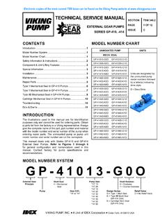
1 SECTION TSM 1 OF 10 ISSUE BVIKING PUMP, INC. A Unit of IDEX Corporation Cedar Falls, IA 50613 USATECHNICAL SERVICE MANUAL CONTENTSINTRODUCTIONThe illustrations used in this MANUAL are for identification purposes only and cannot be used for ordering parts. Obtain a parts list from the factory or a Viking representative. Always give complete name of part, part number and material with model number and serial number of pump when ordering repair parts. The unmounted pump or pump unit model number and serial number are on the the Viking model number system, basic size letters are combined with series number (4195) are used to indicate either an unmounted pump or mounted pump 1KE, KKE, LQE, & LSE 4195 SERIES - Flange & Foot Mounted Unmounted Pumps with Flanged PortsQ & QS 4195 SERIES - Foot Mounted Unmounted Pumps with Flanged PortsIntroduction .. 1 Safety Information.. 2 Special Information.
2 3 Special Mechanical Seals.. 3 Maintenance .. 3 Disassembly .. 4 Assembly .. 7 Thrust Bearing Adjustment .. 8 Installation of Carbon Graphite Bushings.. 8 Pressure Relief Valve Instructions .. 9 UNMOUNTED PUMPUNITSF lange & Foot MountedUnits are designated by the unmounted pump model numbers followed by a letter(s) indicating drive = Direct DriveM = Horizontal Direct DriveR = Reducer DriveKE4195 KKE4195 LQE4195 LSE4195 Foot MountedD = Direct DriveR = Reducer DriveQ4195QS4195 This MANUAL deals only with Series 4195 Heavy Duty Pumps. Refer to Figures 1 through 10 for general configuration and nomenclature used in this MANUAL . Pump specifications and recommendations are listed in Catalog Section 144, Series 4195 and 495 Heavy Duty copies of the most current TSM issue can be found on the Viking Pump website at DUTY PUMPSSERIES 4195 SIZES KE, KKE, LQE, LSE, Q, & QSKE-KKELQE-LSEQ-QSSECTION 2OF 10 BEFORE opening any liquid chamber (pumping chamber, reservoir, relief valve adjusting cap fitting, etc.)
3 Be sure that : Any pressure in the chamber has been completely vented through the suction or discharge lines or other appropriate openings or connections. The pump drive system means (motor, turbine, engine, etc.) has been locked out or otherwise been made non-operational so that it cannot be started while work is being done on the pump. You know what material the pump has been handling, have obtained a material safety data sheet (MSDS) for the material, and understand and follow all precautions appropriate for the safe handling of the operating the pump, be sure all drive guards are in NOT operate pump if the suction or discharge piping is not connected. DO NOT place fingers into the pumping chamber or its connection ports or into any part of the drive train if there is any possibility of the pump shafts being NOT exceed the pumps rated pressure, speed, and temperature, or change the system/duty parameters from those the pump was originally supplied, without confirming its suitability for the new operating the pump, be sure that: It is clean and free from debris all valves in the suction and discharge pipelines are fully opened.
4 All piping connected to the pump is fully supported and correctly aligned with the pump. Pump rotation is correct for the desired direction of hearing protection devices are utilized as the sound level for the pump may be above 85 dBA under certain operating pressure gauges/sensors next to the pump suction and discharge connections to monitor extreme caution when lifting the pump. Suitable lifting devices should be used when appropriate. Lifting eyes installed on the pump must be used only to lift the pump, not the pump with drive and/or base plate. If the pump is mounted on a base plate, the base plate must be used for all lifting purposes. If slings are used for lifting, they must be safely and securely attached. For weight of the pump alone (which does not include the drive and/or base plate) refer to the Viking Pump product NOT attempt to dismantle a pressure relief valve that has not had the spring pressure relieved or is mounted on a pump that is contact with hot areas of the pump and/or drive.
5 Certain operating conditions, temperature control devices (jackets, heat-tracing, etc.), improper installation, improper operation, and improper maintenance can all cause high temperatures on the pump and/or PUMP must be provided with pressure protection. This may be provided through a relief valve mounted directly on the pump, an in-line pressure relief valve, a torque limiting device, or a rupture disk. If pump rotation may be reversed during operation, pressure protection must be provided on both sides of pump. Relief valve adjusting screw caps must always point towards suction side of the pump. If pump rotation is reversed, position of the relief valve must be changed. Pressure relief valves cannot be used to control pump flow or regulate discharge pressure. For additional information, refer to Viking Pump s TECHNICAL SERVICE MANUAL TSM 000 and Engineering SERVICE Bulletin PUMP must be installed in a matter that allows safe access for routine maintenance and for inspection during operation to check for leakage and monitor pump INFORMATION AND INSTRUCTIONSD anger - Failure to follow the indicated instruction may result in serious injury or - In addition to possible serious injury or death, failure to follow the indicated instruction may cause damage to pump and/or other INSTALLATION, OPERATION OR MAINTENANCE OF PUMP MAY CAUSE SERIOUS INJURY OR DEATH AND/OR RESULT IN DAMAGE TO PUMP AND/OR OTHER EQUIPMENT.
6 Viking S WARRANTY DOES NOT COVER FAILURE DUE TO IMPROPER INSTALLATION, OPERATION OR INFORMATION MUST BE FULLY READ BEFORE BEGINNING INSTALLATION, OPERATION OR MAINTENANCE OF PUMP AND MUST BE KEPT WITH PUMP. PUMP MUST BE INSTALLED, OPERATED AND MAINTAINED ONLY BY SUITABLY TRAINED AND QUALIFIED FOLLOWING SAFETY INSTRUCTIONS MUST BE FOLLOWED AND ADHERED TO AT ALL :!!!!!WARNING!!!WARNINGWARNING!WARNING!W ARNING!WARNING!SECTION 3OF 10 SPECIAL INFORMATIONROTATION: The KE QS 4195 series are directional due to the loading groove in the head. This series is designed to operate in CLOCKWISE rotation only. Shaft rotation and head design determines which port is suction and which is discharge. Suction port is where pumping elements (gear teeth) come out of mesh. An arrow on the head of the pump indicates rotation and direction of RELIEF VALVES:1. Viking pumps are positive displacement pumps and must be provided with some sort of pressure protection.
7 This may be a relief valve mounted directly on the pump, an inline pressure relief valve, a torque limiting device or a rupture The relief valve adjusting screw cap must always point towards the suction side of the pump. See Figure Pressure relief valves should not be used to control flow or regulate discharge 2 RELIEF VALVE ADJUSTING SCREW CAPSUCTIONDISCHARGEDANGER !Before opening any Viking pump liquid chamber (pumping chamber, reservoir, relief valve adjusting cap fitting, etc.) Be sure:1. That any pressure in the chamber has been completely vented through the suction or discharge lines or other appropriate openings or That the driving means (motor, turbine, engine, etc.) has been locked out or made non-operational so that it cannot be started while work is being done on pump. 3. That you know what liquid the pump has been handling and the precautions necessary to safely handle the liquid.
8 Obtain a material safety data sheet (MSDS) for the liquid to be sure these precautions are to follow above listed precautionary measures may result in serious injury or additional information on pressure relief valves, refer to TECHNICAL SERVICE MANUAL TSM 000 and Engineering SERVICE Bulletin MECHANICAL SEALS:This bulletin illustrates the mechanical seal which is standard in the catalog 4195 pumps are designed for long, trouble-free SERVICE life under a wide variety of application conditions with a minimum of maintenance. The points listed below will help provide long SERVICE PUMP: Keep the pump as clean as possible. This will facilitate inspection, adjustment and repair work and help prevent overlooking a dirt covered grease : If the pump is to be stored, or not used for six months or more, the pump must be drained and a light coat of non-detergent SAE 30 weight oil must be applied to all internal pump parts.
9 Apply grease to the pump shaft extension. Viking suggests rotating pump shaft by hand one complete revolution every 30 days to circulate the REPAIR TOOLS: The following tools must be available to properly repair Series 4195 pumps. These tools are in addition to standard mechanics tools such as open end wrenches, pliers, screw drivers, etc. Most of the items can be obtained from an industrial supply Soft Headed hammer2. Allen wrenches (set screws & special mechanical seals)3. Mechanical Seal Installation Sleeve 2-751-003-730 for inch seal; KE-KKE 4195 2-751-012-630 for inch seal; LQE-LSE 4195 2-751-005-630 for inch seal; Q-QS 41954. Bearing Locknut Spanner Wrench 2-810-043-3755. Spanner Wrench, adjustable pin type for use on bearing housing end cap. 2-810-008-3756. Brass bar7. Arbor press8. Standard 5/16 12 point socket9. Anti-fretting agent (SKF LGAF 3E)SECTION 4OF 10 FIGURE 3 CUTAWAY FOR MODELS KE, KKE, LQE, & LSE 4195 DISASSEMBLY1.
10 Refer to Figures 4 & 5 for model to be disassembled and name of parts. All 4195 models referenced in this TSM are disassembled and assembled in the same Mark the head and casing before disassembly to insure proper reassembly. 3. Remove the head Tilt the top of the head back when removing to prevent the idler from falling off the idler Remove the idler and bushing assembly. If the idler bushing needs replacing , see Installation of Carbon Graphite Bushings, page Insert a brass bar or piece of hardwood in the port opening and between the rotor teeth to keep the shaft from turning. Turn the locknut counterclockwise and remove locknut. See Figure 6 or 7, page Bend up tang of lockwasher and with a spanner wrench remove locknut and lockwasher from shaft. See Figure 6 or 7, page 6. 8. Loosen the two setscrews in the face of the bearing housing and turn the thrust bearing assembly counterclockwise and remove from casing.