Transcription of TECHNICAL SERVICE MANUAL - vp.salesmrc.com
1 SECTION TSM 000 PAGE 1 OF 8 ISSUE JVIKING PUMP, INC. A Unit of IDEX Corporation Cedar Falls, IA 50613 USATECHNICAL SERVICE MANUAL CONTENTSFIGURE 1 Installation, General Comments 1 Safety Information and Instructions 2 Foundation 3 Alignment 3 Piping 4 Start Up 5 Rapid Wear 6 Troubleshooting 6 Preventative Maintenance 7Do s and Don ts 7 Before installation is started.
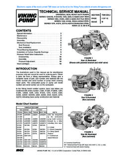
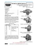
2 A few items of a general nature should be considered 1. Location - always locate the pump as close as possible to the supply of liquid to be pumped Locate it below the liquid supply if at all practical Viking pumps are self priming but the better the suction conditions the better the performance 2. Accessibility - the pump should be located where it is accessible for inspection, maintenance, and repair For large pumps, allow room to remove the rotor and shaft without removing the pump from the base 3. Port Arrangement - since the pumps have different port arrangements depending on the model, port location should be checked before starting the installation The ports may be upright, opposite or at right angles to each other, see Figure 1. The right angle ports are normally right-hand, see Figure 2; some models are available with left-hand arrangements; still other models are available with the right angle ports located in any one of eight positions including right-hand and left-hand 4.
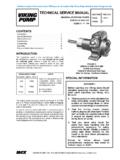
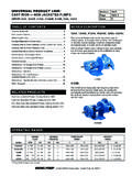
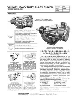
3 Suction/Discharge - shaft rotation will determine which port is suction and which is discharge A look at Figure 3 will show how rotation determines which port is which; as the pumping elements (gears) come out of mesh, point A on Figure 3, liquid is drawn into the suction port; as the gears come into mesh, point B , the liquid is forced out the discharge port INSTALLATIONGENERAL COMMENTSFIGURE 2 FIGURE 35. Pressure Protection - Viking pumps are positive displacement This means that when the pump is rotated, liquid will be delivered to the discharge side of the pump If there is no place for this liquid to go - discharge line is blocked or closed - pressure can build up until the motor stalls, the drive equipment fails, a pump part breaks or ruptures, or the piping bursts Because of this, some form of pressure protection must be used with a positive displacement pump This may be a relief valve mounted directly on the pump, an inline relief valve, a torque limiting device or a rupture disk FIGURE 4 CUTAWAY OF VIKING INTERNAL PRESSURE RELIEF VALVECAPSPRING (A)VALVE BODY (C)POPPET (B)LIQUID OUTLETLIQUID INLETPOINT (E)ADJUSTINGSCREW (D)(SHOULD ALWAYSPOINT TOWARDSUCTION PORT)The pressure relief valve mounted on most Viking pumps and most in-line valves are of the spring loaded poppet design See Figure 4.
4 The spring (A) holds poppet (B) against the seat in the valve body (C) with a given force determined by the spring size and by how tightly it is compressed by the adjusting screw (D). The pump discharge pressure pushes against the underside of the poppet at point (E). When the force exerted by the liquid under the poppet exceeds that exerted by the spring, the poppet lifts and liquid starts to flow through the valve As the discharge pressure builds up, more and more of the liquid flows through until a pressure is reached at which all of the liquid being pumped is going through the valve This pressure is the relief valve setting Reversing the rotation reverses the flow through the pump When determining shaft rotation, always look from the shaft end of the pump Unless otherwise specified, rotation is assumed to be clockwise (CW), which makes the suction port on the right side of the pump The idler pin, which is offset in the pump head, should be properly positioned toward and an equal distance between the port connections Electronic copies of the most current TSM issue can be found on the Viking Pump website at PINSUCTIONABLEFTHANDPUMPRIGHTHANDPUMPINS TALLATION, START UP, TROUBLESHOOTING,PREVENTATIVE MAINTENANCE, DO S & DON TSSECTION TSM000 ISSUEJPAGE 2OF 8 BEFORE opening any liquid chamber (pumping chamber, reservoir, relief valve adjusting cap fitting, etc ) be sure that.
5 Any pressure in the chamber has been completely vented through the suction or discharge lines or other appropriate openings or connections The pump drive system means (motor, turbine, engine, etc ) has been locked out or otherwise been made non-operational so that it cannot be started while work is being done on the pump You know what material the pump has been handling, have obtained a material safety data sheet (MSDS) for the material, and understand and follow all precautions appropriate for the safe handling of the material BEFORE operating the pump, be sure all drive guards are in place DO NOT operate pump if the suction or discharge piping is not connected DO NOT place fingers into the pumping chamber or its connection ports or into any part of the drive train if there is any possibility of the pump shafts being rotated DO NOT exceed the pumps rated pressure, speed, and temperature, or change the system/duty parameters from those the pump was originally supplied, without confirming its suitability for the new SERVICE BEFORE operating the pump, be sure that.
6 It is clean and free from debris All valves in the suction and discharge pipelines are fully opened All piping connected to the pump is fully supported and correctly aligned with the pump Pump rotation is correct for the desired direction of flow INSTALL pressure gauges/sensors next to the pump suction and discharge connections to monitor pressures USE extreme caution when lifting the pump Suitable lifting devices should be used when appropriate Lifting eyes installed on the pump must be used only to lift the pump, not the pump with drive and/or base plate If the pump is mounted on a base plate, the base plate must be used for all lifting purposes If slings are used for lifting, they must be safely and securely attached For weight of the pump alone (which does not include the drive and/or base plate) refer to the Viking Pump product catalog DO NOT attempt to dismantle a pressure relief valve that has not had the spring pressure relieved or is mounted on a pump that is operating AVOID contact with hot areas of the pump and/or drive Certain operating conditions, temperature control devices (jackets, heat-tracing, etc )
7 , improper installation, improper operation, and improper maintenance can all cause high temperatures on the pump and/or drive THE PUMP must be provided with pressure protection This may be provided through a relief valve mounted directly on the pump, an in-line pressure relief valve, a torque limiting device, or a rupture disk If pump rotation may be reversed during operation, pressure protection must be provided on both sides of pump Relief valve adjusting screw caps must always point towards suction side of the pump If pump rotation is reversed, position of the relief valve must be changed Pressure relief valves cannot be used to control pump flow or regulate discharge pressure For additional information, refer to Viking Pump s TECHNICAL SERVICE MANUAL TSM 000 and Engineering SERVICE Bulletin ESB-31 THE PUMP must be installed in a matter that allows safe access for routine maintenance and for inspection during operation to check for leakage and monitor pump operation WARNINGSAFETY INFORMATION AND INSTRUCTIONSD anger - Failure to follow the indicated instruction may result in serious injury or death Warning - In addition to possible serious injury or death, failure to follow the indicated instruction may cause damage to pump and/or other equipment IMPROPER INSTALLATION, OPERATION OR MAINTENANCE OF PUMP MAY CAUSE SERIOUS INJURY OR DEATH AND/OR RESULT IN DAMAGE TO PUMP AND/OR OTHER EQUIPMENT.
8 VIKING S WARRANTY DOES NOT COVER FAILURE DUE TO IMPROPER INSTALLATION, OPERATION OR INFORMATION MUST BE FULLY READ BEFORE BEGINNING INSTALLATION, OPERATION OR MAINTENANCE OF PUMP AND MUST BE KEPT WITH PUMP. PUMP MUST BE INSTALLED, OPERATED AND MAINTAINED ONLY BY SUITABLY TRAINED AND QUALIFIED FOLLOWING SAFETY INSTRUCTIONS MUST BE FOLLOWED AND ADHERED TO AT ALL :!!!!!WARNING!!!WARNING!WARNING!WARNING! WARNING!SECTION TSM000 ISSUEJPAGE 3OF 8 CAUTION !Internal type relief valves mounted on Viking pumps should always have the cap or bonnet pointed toward the suction side of the pump. Return-to-tank type relief valves should always be mounted on the discharge side of the pump. If pump rotation is reversed, change the relief valve. Turn the internal type end for end; move the return-to-tank type to the other port. If on a particular installation rotation is reversed, , using one pump to fill a tank and then by use of a reversing switch or other means of changing the rotation to permit the same pump to circulate the liquid through a heater or to load out, then pressure protection must be provided on both sides of the pump for both rotations.
9 This may be a combination of relief valves, torque limiting devices or rupture : On some models, the relief valve is mounted on the pump casing instead of the pump spring loaded poppet-type valve is strictly a differential valve, sensing only those pressures on each side of the poppet It should not be used as a pressure or flow control device It is intended strictly as a relief pressure at which either the return-to-tank or internal relief valve bypasses can be changed by turning the adjusting screw Do not back the adjusting screw all the way out Stop when spring tension is off the screw (the screw starts to turn easily) For details on maintenance of the relief valve, see TECHNICAL SERVICE MANUAL covering your model series 6. Motor - follow local electrical codes when hooking up motors FIGURE 5 AINTERNAL PRESSURE RELIEF VALVEFIGURE 5 BRETURN-TO-TANK PRESSURE RELIEF VALVECAUTION !
10 Pumps or systems without relief valves should have some form of pressure protection, torque limiting devices or rupture pumps can be furnished with either an internal pressure relief valve - one which directs the flow from the valve back to the suction side of the pump - or a return-to-tank valve - which directs the flow through piping back to the supply tank See Figures 5A and 5B. An inline relief valve mounted in the discharge piping also directs the flow back to the supply tank This type of valve should be mounted close to the pump so that the pressure drop through the piping between the pump and the valve is at a minimum Be sure there are no shutoff valves between the pump and relief valve Piping from a return-to-tank or an in-line valve to the supply tank should also be as short and as large as possible FOUNDATIONE very pump should have a solid foundation It may be any structure sufficiently strong to hold the pump rigid and to absorb any strain or shock that may be encountered A certified print of the pumping unit should be used in preparing the foundation If a separate foundation is provided, make it at least four inches wider and longer than the base of the unit When the unit is placed on the foundation.