Transcription of Technical Specifications Rev. F - 02/2021 Masoneilan 35002 ...
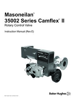
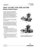
1 Technical Specifications Rev. F - 02/2021 Baker Hughes Data Classification : PublicMasoneilan 35002 Series Camflex II rotary Control ValvesComplete line of eccentric plug control valves effectively combining enhanced control performance, simplicity and long-term reliability for a broad range of applications. 2021 Baker Hughes. All rights | Baker Hughes 2021 Baker Hughes. All rights 35002 Series Camflex II rotary Control valves Tech Spec | 1 Table of contentsFeatures ..1 Numbering System ..2 Actuator Mounting Guide ..3 General Data / Ratings and Connections ..4-6CV and FL Versus Travel ..6-7CV Versus Travel ..8 Materials of Construction ..9-13 Dimensions and Weights ..14-15 FeaturesThe Camflex II valve is a heavy-duty, automatic-throttling control valve that incorporates the following features: The flangeless body rating is a rugged ASME Class 600. Heavy-duty guide lugs assure quick, positive alignment during installation. The flanged version is available in 1 in.
2 Through 12 in. (25 mm through 300 mm) sizes in 150 or 300 ASME, and 1 in. through 8 in. (25 mm through 200 mm) in 600 ASME. The optional Camflex GR (Globe Replacement) version is available in 1 in through 6 in. sizes (25mm through 150mm) in ASME Class 150, 300, and 600 ratings and allows direct replacement of conventional reciprocating globe valves . Separable bonnet design is available. Straight through flow pattern provides greater flow capacities. Standard integral extension bonnet allows for a wide range of fluid temperature applications (-320 F to 750 F), (-196 C to 400 C). The unique self-aligning eccentric rotating plug provides tight shutoff and low dynamic forces. A large variety of reduced-trim options are available in all sizes. The triple, over-sized bearing system provides exceptional plug shaft guiding. The shouldered shaft design provides robust blowout prevention. An optional patented differential velocity device (DVD) separates compressible flowstreams into a high velocity core and a low velocity envelope flowstream.
3 This provides up to 18 dBA noise attenuation. Optional alloy constructions are available. The powerful, low-profile, spring-diaphragm actuator guarantees positive fail-safe action. Splined shaft and actuator linkages, combined with low-friction techniques, contribute to reduced deadband and hysteresis. The valve position indicator is large and highly visible. The actuator linkage (purge option available) is totally enclosed). 2021 Baker Hughes. All rights | Baker HughesTrim TypeDesignNumbering system1st2ndActuator Type 1. Parallel to pipeline, valve closes on stem extension. 2. Parallel to pipeline, valve opens on stem extension. 3. Perpendicular to pipeline, valve closes on stem extension. 4. Perpendicular to pipeline, valve opens on stem extension. 5. Parallel to pipeline, valve closes on stem extension. 6. Parallel to pipeline, valve opens on stem extension. 7. Perpendicular to pipeline, valve closes on stem extension. 8. Perpendicular to pipeline, valve opens on stem Mounting(see guide on page 3)Body Series35SB (optional separable bonnet)GR(optional Globe Replacement face to face)2 Design Series 1.
4 Metal Seat 2. Soft Seat 3. Metal Seat w/ Differential Velocity Trim 4. Soft Seat w/ Differential Velocity Trim20 Manual Actuator35 Spring-opposed rolling-dia-phragm4th3rd5th2nd1st352 2021 Baker Hughes. All rights 35002 Series Camflex II rotary Control valves Tech Spec | 3 Actuator mounting guideNotes Standard actuator mounting positions are shaded in grey. Plug positions are shown in the initial position without air on actuator. The actuator must be always mounted above the pipeline. It is recommended that the actuator always be mounted as shown above. For other positions, consult your local sales office. Installation is assumed to be in the horizontal pipeline for orientation of the airset and other accessories unless specified on the order. Action and orientation are field reversible without additional parts. Operating efficiencies may vary depending on valve configuration. The above schematic does not reflect every possible body/actuator orientation, but should serve as an effective Flow DirectionFlow-To-CloseAIR-TO-CLOSEAIR-TO -CLOSER ecommended Flow DirectionCamflex II Control valves (Mounted on Horizontal Pipeline) Position in Relation to Valve BodyNumbering System : 1 to IIPlugPositionPlugPositionPlugPositionPl ugPositionNOTES :2.
5 Standard actuator mounting positions are shaded :2. Plug positions are shown in the initial position without air on The actuator must be always mounted above the pipeline. 2021 Baker Hughes. All rights | Baker HughesGeneral dataBodyType: cast with integral bonnet cast with separable bonnet 1 in. Flow Direction: flow to open or flow to close (Differential Velocity Device trim flow to open only)Materials: carbon steel 316 stainless steel (flangeless) 316L stainless steel (flanged) Hastelloy C (1 in.) (DN 25-100)1 Body Pressure Rating: ASME Class 600 (per ) standard (1 in.) (DN 25-300), except for flanged construction: valve rating is limited by flange ratingEnd Connections: threaded NPT for ASME Class 600 rated connections (1 in.) (DN 25) flangeless clamps between ASME Class 150, 300 or 600 rated flanges (flange rating must be specified for 8 in. (DN 200-300) valve for locator lug drilling and tapping) flanged - bolts to ASME Class 150 or 300 rated flanges (1 in.)
6 (DN 25-300) ASME Class 600 rated flanges (1 8 in.) (DN 25-200) GR flanged - bolts to ASME Class 150, 300 or 600 rated flanges (1 in. - 6 in.) (DN 25-150)TrimPlug Type: self-aligning eccentrically rotatingMaterials: 1 in. (DN 25-100): solid Stellite No. 6 3 in. (DN 80 & 100): solid Stellite No. 6 optional 3 in. (DN 80-300): 316L stainless steel with hardfaced seating surface 1 in. (DN 25-100): Hastelloy C1 Seat Ring: solid clampedMaterials: 1 in. (DN 25-300): 316 stainless steel 1 in. (DN 25-100): Hastelloy C1 1 in. (DN 150-300): 316 stainless steel with hardfaced seat 1 in. (DN 25-100): solid Stellite No. 6 optional 1 in. (DN 25-300): 316 stain-less steel with PTFE insert (to 450 F), (232 C)2 1 in. (DN 25-300): 316 stainless steel with PCTFE insert (-50 to -320 F), (-46 to -196 C) Retainer: 316 Stainless SteelCapacity: full area and reduced capacity in all sizesFlow Characteristic: standard trim: linear low flow trim (.)
7 036 + .07 factor): linear (requires SVI) differential velocity device: linearCV Ratio: standard trim >100:1 low flow trim 15:1 differential velocity device >50:1 ActuatorsSpring-Opposed Rolling DiaphragmSize: 4 in. diameter with 3 in. (89mm) stroke (1 in. valves ), (DN 25-50) 6 in. diameter with 5 in. (146mm) stroke (3 in. valves ), (DN 80-100) 7 in. diameter with 7 in. (184mm) stroke (6 in. valves ), (DN 150-300) 9 in. diameter with 7 in. (184mm) stroke (6 in. valves ), (DN 150-300) Range: 7-15 psi (1 in.), (DN 25-100) 7-24 psi (6 in.), (DN 150-300) (7 in. diameter actuator) 7-24 psi (6 in.), (DN 150-300) (9 in. diameter actuator, Air to Close) 8-25 psi (6 in.), (DN 150-300) (9 in. diameter actuator, Air to Open)Air Connection: 1 4 in. NPTYoke: cast ironBearing: sealed radial Auxiliary Handwheel: solid disk with locking nut: 62 5 in. diameter (1 in. valves ), (DN 25-100) 10 in.
8 Diameter (6 in. valves ), (DN 150-300)Manual ActuatorType: Solid disk with detent anti-rotation device. Continuously : 7 in. (178mm) diameter (1 in. valves ), (DN 25-50) 87 8 in. (225mm) diameter (3 in. & 4 in. valves ), (DN 80-100) 161 8 in. (410mm) diameter (6 in. valves ), (DN 150-300)Material: aluminumYoke: cast ironBearing: sealed radial ball1. See materials of construction2. Not available in .2 factor or Low Flow Trim sizes 2021 Baker Hughes. All rights 35002 Series Camflex II rotary Control valves Tech Spec | 5 General dataStandard Spring Diaphragm Actuator MaterialsDescriptionMaterialYokeCast IronYoke CoversPolycarbonateSpring BarrelDie Cast AluminumDiaphragm CaseDie Cast AluminumPistonDie Cast AluminumDiaphragmBuna-N with Dacron InsertPiston Rod303 St. Steel Zinc Dichromate PlatedClevis Pin17-4 PH (H1075) St. With Epoxy SurfaceLever BearingPTFE Filament Surface Bonded to Glass Reinforced Plastic BackingHandwheel and LocknutAluminumStandard Actuator Characteristics and Travel Times[Measured with direct positioner at 30 psi (2 bar) supply, 4700P positioner with tubing size in.]
9 ]Actuator DiameterDiaphragm Effective AreaActuator StrokeTravel Time (sec.)Increasing Instrument SIgnalDecreasing Instrument LeakageValve SizeSeat TypeTemp. Range1 Max. Seat Leakage, ASME F1 (-196 C)+750 F (400 C)IVSoft Seat2-320 F1 (-196 C)+450 F (232 C)VI1. For Stainless Steel Bodies Temperature limited by PTFE/PCTFE F (400 C)650 F (340 C)550 F (300 C)450 F (230 C)350 F (180 C)250 F (120 C)150 F (70 C)Temperature Gradient Across Standard Integral BonnetThe ability of the Camflex valve to handle a wide range of process fluid temperatures is due to the long, integrally-cast bonnet. This affords ample radiation surface to normalize the packing Rated Flow Coefficients (CV) and Critical Flow Factors (FL) at Maximum Opening (50 )Valve SizeFactorFlow to OpenFlow to CloseinchesDNRated CvFLRated : Low flow trims (.036+.07 factor) require use of SVI II AP or SVI FF digital positioners. 2021 Baker Hughes. All rights | Baker HughesCV and FL versus travelFlow Direction: Flow to OpenFlow Characteristics: LinearASME Class: 150 through 600 Sizes: 1 in.
10 Through 12 in. (DN 25-300)Ratings and connectionsNote: For flangeless valve sizes 8 in., (200mm-300mm), please specify ASME Class to Face: ISA SizeASME m l os m l os m l o3-680-150 m l o m l o m l o880-200m lm lm l10-12250-300m lm lms Threaded m Flangeless l RF Flanged o GR FlangedPercent of Plug Rotation102030405060708090100FL Full Reduced Area (.6, .4, & .2) SizeOrifice Diameter TravelRated 2021 Baker Hughes. All rights 35002 Series Camflex II rotary Control valves Tech Spec | 7CV and FL versus travelFlow Direction: Flow to CloseFlow Characteristics: Linear ASME Class: 150 through 600 Sizes: 1 in. through 12 in. (DN 25-300)Percent of Plug Rotation102030405060708090100FL Full Reduced Area (.6, .4, & .2) SizeOrifice Diameter Act. Stem TravelRated 2021 Baker Hughes. All rights | Baker HughesCV versus travelDifferential Velocity Device (DVD)Flow Direction: Flow to Open onlyFlow Characteristics: LinearASME Class: 150 through 600 Sizes: 1 in.