Transcription of TECHNICAL TOPIC STUDENT MINIMISING …
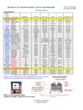
1 10 NAPIT0870 444 1392 444 1392 11 STUDENTFor example, in Fig 1, a cable which is protected by aBS 3036 rewireable fuse is first grouped together withother cables, then it is totally surrounded by thermalinsulation for a distance of more than metres. Thenfinally it is run through an area with a high ambienttemperature. As the BS 3036 fuse affects the whole cablerun, Ctmust be applied. However, there is no need toapply the other three factors as the worst factor alone willbe sufficient. Let s take the grouping factor to be , thethermal insulation factor to be and the ambienttemperature factor as , as indicated in Fig 1.
2 In thiscase, only Cr= and Ci= need to be factors for grouping and ambient temperature x = As the factor for thermal insulation islower ( ), this is the only factor used for the conditionsalong the cable run. InIt> Cix Cr4 The current-carrying capacity of the cable (which istermed Iz) is then selected from the appropriate tablein Appendix 4 of BS 7671. Izshould be at least equalto or slightly greater than the tabulated current, the voltage drop to ensure that it is notexcessive. Regulation 525-01-02 states that thevoltage drop from the origin of the supply to thefurthest point in the installation must not exceed fourper cent of the supply voltage when the conductorsare carrying full load current.
3 The tables in Appendix 4have a voltage drop section in which the millivolt peramp per metre (mv/a/m) of a particular cable may beobtained. The voltage drop is calculated from:Volts drop = mv/a/m x design current, Ibx length of run in metres, L 1000As four per cent of the nominal 230 volts single-phasesupply voltage is volts, this figure must not beexceeded for single-phase any electrician about the required cross-sectionalareas of cables for standard circuits and the answeryou receive will probably be along the lines of: 1mm2or mm2for lighting circuits and mm2forsocket-outlet circuits.
4 Indeed these are the commonly used rule ofthumb , those who undertake electricalinstallation work need to understand the procedurefor selecting the correct cross-sectional area of acable for a particular use. It is the intention of this article to explain simplyhow to select the correct cross-sectional area ofcables with particular single-phase loads in ll refer to the tables in Appendix 4 of BS 7671,although these tables are reproduced in Appendix 6of the IEE On Site Guide. We ll assume that theovercurrent protective device will be providing faultcurrent and overload current which is the the right size There are five steps to calculating the right size ofcable for a particular load.
5 These are as follows:1 Calculate the design current (Ib). This is the normalcurrent drawn by the load. It is usually determinedasfollows:Ib =WattsVolts2 Select the type and current rating of theovercurrent device (In). 3 Apply the relevant correction factors to obtain thetabulated current (It).Correction factors are applied to situations whichinhibit a cable from dissipating its heat caused bythe normal flow of current through it. Therefore,the following correction factors, if applicable, areapplied:Ambient temperature, CaThis factor is obtained from Table 4C1 (or Table 4C2 ifa rewireable fuse to BS 3036 is used) in Appendix 4 ofBS 7671.
6 Grouping, CgThis factor is found by reference to Table 4B1 inAppendix 4. Table 4B2 is used where mineralinsulated cables are installed on perforated cable tray. Thermal insulation, CiWhere a cable is in contact with thermal insulation onone side only, the current-carrying capacity of thecable should be calculated using Reference Method4, which is described in Appendix 4 (Table 4A) of BS7671. Where a cable is totally surrounded by thermalinsulation for a distance greater than metres, thecurrent-carrying capacity should be taken, in theabsence of further information, as times thecurrent-carrying capacity for that cable when usingInstallation Method 1 (open and clipped direct).
7 Where a cable is totally surrounded by thermalinsulation for a distance of metres or less, Table52A in BS 7671 gives derating factors which must beapplied. Rewireable fuse (BS 3036) factor, CrWhere a rewireable fuse to BS 3036 is used, a furthercorrection factor of is applied, due to the poorfusing factor of rewireable to apply correction factorsThese correction factors are applied as divisors to thenominal current rating of the overcurrent protectivedevice (In), to obtain the tabulated current, It. Forexample, in the worst possible situation where all fourfactors are applied, the formula would look like this:InIt> Cax Cgx Cix CrThe more correction factors we apply, the larger thevalue of It will be and hence the larger the size ofcable we will require.
8 Consequently, it isadvantageous to avoid having to apply correctionfactors where possible by, such measures as,avoiding grouping of cables and avoiding contactwith thermal the formula given above is based on theassumption that the conditions requiring theapplication of correction factors apply simultaneouslyto the same part of the cable along its route. Where particular correction factors are appropriateto different parts of the cable along its route, each partcan be treated separately. Alternatively, only thecorrection factor (or combination of factors)applicable to the worst situation along the cable routecan be applied to the whole route.
9 (See Item ofAppendix 4 in BS 7671) TECHNICAL TOPIC MINIMISING VOLTAGE DIFFERENCESS hort guide to working out cable sizesIn the first of twoarticles, Bill Allanlooks at thecorrect method incross-sectionalwork, a job thatrequires a headfor calculationsanda steadyhand( )BS 3036 fuseGroupingThermalinsulationAmbienttemp eratureFactor( )Factor( )for distancesover metresFactor( )LoadConsumerunitFig 1 Worked example1A 6kW load is to be supplied at 230 V by a PVC sheathed andinsulated twin and cpc copper cable, 8 metres in length. The cable isclipped on the surface through an area with an ambient temperatureof 40 C and is grouped with three other cables of similar size andloading.
10 The protection is by means of a BS 3036 fuse. Calculate theminimum cable size required (it is assumed in this example that all thecorrection factors need to be applied).AnswerW6000 Design current, Ib= = = 26 ampsV230 Size of BS 3036 fuse required = 30 amps (In)InTabulated current, It> correction factorsFrom Table 4C2,Ca= Table 4B1, (4 circuits, Method 1)Cg= factor for BS 3036 fuse = > Cax CgxCrIn> x x > ampsFrom Table 4D5A (Reference Method 1, column 4), select 16 mm2cablewhich takes 85 volts drop from Table 4D2B (column 3).