Transcription of TECHNICAL TOPIC STUDENT MINIMISING VOLTAGE …
1 10 NAPIT0870 444 1392 the previous issue of The Competent Personmagazine, we considered the five basic steps forworking out the correct size of cable for a particularload. Due to the importance of this subject, we oughtto consider it further. In particular, we ll look at thecross-sectional areas of neutral conductors andprotective conductors. Co-ordination between conductorand protective deviceRegulation 433-02-01 in Section 433 contains therequirements for the relationship between theconductor and the overcurrent device which protects terms included in this Regulation are:Ib= the load currentIn= the nominal current rating of the overcurrentprotective deviceIz= the current-carrying capacity (that is, the currentrating) of the conductorsI2= the current causing effective operation of theovercurrent protective device. That being said, Regulation 433-02-01 can besummarised as follows:(i)In>Ib(ii)Iz>In(iii) x Iz>I2 Regulation 433-02-02 states that, for the followingdevices, compliance with condition (ii) above resultsin compliance with condition (iii).
2 In other words, forthe following devices, I2is deemed to be less x Iz: type (gG) fuses to BS fuses to BS 88-6 fuses to BS 1361 circuit-breakers to BS EN 60898 circuit-breakers to BS EN 60947-2 RCBO to BS EN 61009-1 Regulation 433-02-03 concerns rewireable fuses toBS 3036 and may be summarised like x Iz>InCross-sectional areas of neutralconductorsSection 524 of BS 7671 contains generalrequirements for cross-sectional areas of phaseconductors and neutral conductors. In single-phasecircuits, the cross-sectional area of the neutralconductor must not be less than that of the phaseconductor. In three-phase circuits, the size of neutralconductors may be reduced provided that thedesigner has assessed that the current in the neutralconductor will be less than that in the phaseconductors. However this reduction of the neutralconductor is becoming less common due to theharmonic content of modern electrical loads.
3 In anycase, the practice is not permitted for dischargelighting circuits. Cross-sectional area of protectiveconductorsThe requirements for determining the cross-sectionalareas of protective conductors are found in Section543 of BS 7671. The first regulation in this Section,Regulation 543-01-01 contains two basic methods fordetermining the cross-sectional area of protectiveconductors:1It can be selected using the adiabatic equation, or2 It can be selected using Table 54G. 1 The adiabatic equationThe adiabatic equation is given in Regulation 543-01-03 and looks like this:I2tS= kwhere, S = the cross-sectional area of the protectiveconductorI =the fault currentt = the operating time of the overcurrent devicecorresponding to the fault currentk = a factor which takes account of the resistivity,temperature coefficient and heat capacity of theconductor materialTECHNICAL TOPIC MINIMISING VOLTAGE DIFFERENCESG uide to working out cable sizes 2In part two inthis series, Bill Allancontinues hislook at thebasic stepsand providesexamples totest yourknowledgeStudentActivities1 Study Regulation 433-02-01 of BS 7671 andsummarise the requirements regarding the co-ordination between conductor and protective Section 524-02 of BS 7671 and summarisethe requirements regarding the cross-sectional areaof neutral Section 543-01 of BS 7671 and summarisethe requirements regarding the cross-sectional areaof protective conductors.
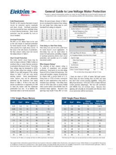
4 4 Use the adiabatic equation to determine theminimum cross-sectional area of a circuit protective 2 Table 54 GIf the adiabatic equation looks like too much trouble, then the good news is thatyou can use Table 54G of BS to Table 54G shows that, where the associated phase conductor has across-sectional area up to and including 16 mm2, the protective conductor can beof the same cross-sectional area. In the worked example above, the cross-sectional area of the associated phase conductor is 4mm2. This means that, usingTable 54G would require the protective conductor also to have a cross-sectionalarea of 4 mm2. This size is clearly considerably larger than the mm2whichwas selected using the adiabatic equation method. It is however much quicker andeasier to use Table Activities (left) contains more examples, together with the answers, if youneed the to STUDENT Activities from Issue 2: 1, ; 2, ; 3, ; 4, ; 5,Column 2; 6, amps; 7,15 444 1392 11 Thismight look quite daunting but a worked exampleis the best way to show how it sizes 2 Worked exampleUse the adiabatic equation to determine theminimum cross-sectional area of a circuitprotective conductor suitable for use on a radialcircuit protected by a 30 amp fuse to BS 230 volt circuit is wired in single-core 70 CPVC insulated cables with copper conductors,which are installed in steel conduit.
5 The cross-sectional area of the phase and neutralconductors is 4 mm2. The earth fault loopimpedance Zsis current, If= = = 160 disconnection time, t, is found by referenceto the appropriate time/current characteristic ofa 30 amp BS 3036 fuse. This is found in in Appendix 3 of BS 7671. Thesetime/current curves make use of logarithmicscales, which enable large scales to be used ina relatively small area. The disconnection time isapproximately seconds. The value of k isobtained from Table 54C of BS 7671 and is the adiabatic equation can be used asfollows:I2t160 2x = = = mm2k115 NoteIt is only the top line which is square rooted not the whole areaof phase conductor,S(mm2)where: k1is the value of k for the phase conductor, selected from Table43A in Chapter 43 according to the materials of both conductor the value of k for the protective conductor, selected from Tables 54B,54C, 54D, 54E or 54F, as <1616 < S <35S>35If the protectiveconductor is of the same material as thephase conductor(mm2)S16S 2If the protectiveconductor is not ofthe same material asthe phase conductor(mm2)k1 x Sk2k1 x 16k2k1S x k22 Minimum cross-sectional area of thecorresponding protective conductorTable 54 GMinimum cross-sectional area of protective conductor in relation tothe cross-sectional area of associated phase conductorconductor suitable for use on a radial circuitprotected by a 20 amp fuse to BS The 230volt circuit is wired in 70 C PVC insulated andsheathed flat cable with a protective conductor(copper conductors).
6 The earth fault loopimpedance Zsis ohms. (Assume k to be 115).