Transcription of TECHNICALTOPIC TTsystem s:rightwa - napitonline.com
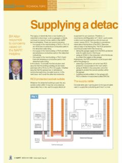
1 8 NAPIT087 0 44 4 1392ww All anfo llowsupinq uir ies onthe NAPITH elplinean dlo oks indetailat thedemandsofBS76 71 onthis lin e ofworkPhase toearth faultPNPNP haseconductorNeutralconductorSupplytrans formerGroundlevelEarthelectrodeArrows indicate thepathof the fault currrentEarthconnectionblockNeutralconne ctionblockMeterConsumerunitEarthingcondu ctorTT supplyMainearthingterminal ( )MainearthingconductorEarthelectrodeMain equipotentialbondingconductorsItemof electricalequipmentP N N Pmainswitchwitha 100mA RCDincorporated30mA RCDFi g 1 TTsyst em s: ri ght waTEC HNI CA L TOPI CEnqu iries regardingelectricalin stallationsformingpart of TT sy stem s con tinu e to keep the NAPITT echn ic al Helplinebusy. We co vered the topicin agene ral way in last issu e sAsk Eddiebu t in thisartic le I ll go in to mo re detailan d reviewtherequ irem en ts of BS 7671 fo r suchinstal latio ns,answ erin g typicalqu estio ns in the temsElec tric al in stallations fo rm ing part of a TT systemare co mmonly fou nd in older pr oper ties and areasoflo w po pu latio n den sity an d may be suppliedbyove rh ead cab les or under gr ou nd earthispro vided fro m th e so ur ce of supplyandcon sequ ently , prem ises have their own earthelec tr ode.
2 Expo sed- condu ctive-partswit hin the inst allationare co nn ectedvia pro tectiveco ndu ctor s to the maineart hin g term inal (MET)and fr om th e MET to theeart h electrode. In the eventof a ph ase to earth fau ltocc urrin g in the installation , th e ear th fault currentflow s back to the sou rce as sho wn in Fi g. syst ems are also used in electrical installationswher e th e de signerco nsiders it inadvisableto useth e ear th ing facilitypr ovidedby the electricitysu pplier,particularly if the earth ing facilityis providedfro m a PME netw ork. Examples are: sw immingpools and rem ote bu ildingswith extraneous-condu ctiv e- onReg ulatio n 413-02 -19 of BS 767 1 st ates that whileoverc urrent prot ec tive devicesmay be used,RCDsare pref is because th e earthfault loopim pedance (Zs) valu es for eac h circu it ar e unlikelyto be le ss th an th e maxim um Zsvalue s relate d to thevario us typesan d ratingsof overcurr ent devices inTab les 41B1, 41B2 and 41D of BS ore au to mat ic disconne ct io n byoverc urrent dev ic es wit hin or 5 secondscannotbe guaranteed.
3 The requ irem ent fo r eachcircuitininst allations form in g part of TT systemsis giveninReg ulatio n 413-02 -20:RAIa 50 Vwhere:RAis the su m of th e resistances of th e ear thele ctrode and th e pro tectiveco ndu ctor(s)connec ting it to th e expo the curre nt cau sing aut om atic operat ion of theNAPIT0870 444 1392ww tectiv e device wit hin 5 ere th e pro te ct ive deviceis an RCD,Iain th e(belo w left) for mu la is the rate d residual ope ratingcurren t I nof the sh ou ld be note d that the 50 volt valueismodi fied for cert ain locations in Part 6 of fore , wh ile aut omaticdisconnectioninins tallationsfor min g part of TT syst ems is notspec ific ally stat ed in term s of maximum time ( or 5 sec ond s) , fro m the abovefo rmulait may betaken to be eith er five seconds(w here overcurrentpro tectiv e devices are used) or, where RCDsareused,th e I nof the RCD (.)
4 3 se con ds for a 30mA RC D or 0. 1 secondsfor a 10 0 mA RCD).Maximumvaluesof earthelectroderesistanceThe max imumpe rmissable re sist an ce valuesof theearthelectrode may be takenfro m Table1,reproduc ed from Tab le in IE E GuidanceNot e 3,Inspection an d valu es in Tabl e 1 ar e basedon th e formulainRegu latio n 41 3- 02- 20 : RAIa 50 example, whe re a 30 mA RCD is used in anormaldry loc atio n, the maximum valueof the earthelec tr ode resistance,RAwill be as fo llo ws:RAIa 50 VV50 The ref or e: RA (th e corre spon ding valu e in th e tablebelowhasbeen ro unded do wn slig htly)ayto designand testPNPNE arthconnectionblockNeutralconnectionbloc kMeterConsumerunitEarthingconductorTT supplyP N N Pmain switch witha 100mA RCDincorporated30mARCDP haseconductorNeutralconductorSupplytrans formerGroundlevelEarthelectrodeMain earthing terminal(disconnected from )EarthelectrodeMainequipotentialbonding conductorsTestinstrumentFig 2 Tabl e1.
5 Max imum values of earth electrodere si st ance for TT installationsRCD rat edre si dualop erati ngcurre nt InMax imum value sof earthelect rod ere si st ance, RAnormal drylocationsconstructionssites, agricultu ra land horticultura lpremises30 mA1660 830 100 mA500 250 300 mA160 80 500 mA100 50 Con tinu edonPage 10 Meas ur ingearth el ectro dere si sta nceTw o met ho ds are givenin IEE GuidanceNote3,In spec tio n an d Testingfo r measuring th e resistanceof installation earthele ctro des: te st meth od 1, in which only the resistanceof theele ctro de and th e eart hin g conductor connectedto it are measu red, is use d wh ere a high level ofac curac y is im po rtant and where low valuesofele ctro de re sistanceto earthare req uire d, as inele ctro des used in th e ear thin g of sub-stations,gen erato rs an d tran sfor mer s. Te st method1in vo lv es the use of a pro priet ary te st instrument.
6 Te st meth od 2, in which th e im pedance of thewhole earthfau lt cu rren t pat h is measuredand istak en to be th e resistanceof th e ele od is used whe re a high level of accuracyisnot stric tly requ ired an d invo lv es th e use of astan dard ear th loo p im pedancetest is mor e usu al for test met ho d 2 to be usedtome asur e elect rode resistan ce in TT sys temsas theelec tr ode un der test is usedin co nju nctionwith anRC D, which is likelyto provideauto maticdisc on nection in th e eventof a fault,even with arelat ive ly high valu e of ele ctro de re sequ ently , th is articlewill deal only with testme th od r to st artingthe test , th e inst allation mustbeiso latedfro m th e su pply and th e eart hin g conductorto th e earth electrode mu st be disconne cted at themaineart hin g term inal so that th e re adingis notaf fec ted by parallelpath s.
7 The eart h loop impedancetest er is co nn ectedbet wee n th e in co minglive phasecon duc tor and th e earth ing co ndu ctor to theelec tr ode (F ig. 2) . As th e resistanceof the electrodeis likelyto be significantly high er th an the othercom po nen ts of th e ear th fault curr ent pa th, thereading is take n to be RA. The elec tric al resistancetoeart h (RA) is rec orded in th e spacepro videdon thecertif ic ate .In orde r to allo w for dry weath er cau sing a rise inso il resistance, IEE Guidance Not e 3 advisesthatresistanc e valu es of eart h electrode shouldbe below200 ohm s. Ho we ve r, as BS 7430: Co de of Practicefor Earth ing recomme nds th at the resistancevaluesh ou ld no t exceed100 ohms, this lowervalueispref er able .Recordingva luesQue stion s hav e be en askedon th e NAPITT echnicalHelplinesu ch as: Do I also needto inser t a valueforZe?
8 And Is Zeth e sam e as RAin TT systems? Ref er enc e to Fig . 1 sh ow s th at this test is clear lydif ferentto a Zetest in a TN-S or TN-C -S syste ev er, th e measu rem ent (wh ich is takento be RA)cou ld be considered to be th e equ ivalentof Zein TN S and TN-C-S sy stem it is a requ irem ent of Regu latio n 313-01-01th at th e valu e of Ze be determined,thevalueofRAshouldalsobe recordedonthecertif icate le 1 sh ows th at th e use of RCDs for automaticdisc on ne ctio n perm its much high er valuesof RA(Ze), and th ere fore of Zs, than could be allo wedwhen usin g overc urren t pro tectivedevicesforindirect sh ock pro tection. Co nsequently,somehaveaskedth e qu estio n: Is it necessaryto carr y out Zstestson TT inst allations? It is a requ irem ent of Regu lation71 3-11-01thatZsbe exceptions are madefor TTsy stem s. Theref ore, wher e installations whichformpart of TT systems are be ing testedand certificated,Zstestssh ould still be carriedout and re co rded onthe cer tific at e, eve n if the va lue s exc eed the max im umZsva lues in Tabl es 41 B1 , 41B 2 and 41D of BS 767 ant age s to me asuring Zsare th at thecon tinu ity of th e circuit pro tectiveco nductoriscon fir med and deterioratio n can be asse ssedonsu bse quen t a typic al splitboard co nsu mer unit for TTsy stem , th e so cket-o ut let circu its are protected by ado wnst ream30 mA RCD, which is requiredbyReg ulatio n 471-08-06 (th is regu latio n sh ould bestu died for th e full requ irem ents).
9 Th e othercir cuit sare pro tec ted by an upstreamtim e-delay(S type)100 mA the 10 0 mA RCD necessary? Yes, if the Zsvalue s for tho se oth er circu its are to o high to permitdisc on ne ctio n within th e requ ired tim th e ro le of RCDs are vital in ensu ring protectionag ainst elec tric sh ock in TT syst ems,it is of theutmo st im po rtanc e that th ey are pro perlytestedinac cordan ce wit h BS rth er informationonRC Ds can be foundin IEE Gui danc e Note 1,Sel ection and Erec tion (Sec ti on 3. 6), whilethe topicof aut oma tic disconnecti on is cov ered in somedet ail in IEE Gui danc e Note 8, Earthi ng and Bonding(Cha pter 7) . See also story on Pa ges 22 and 23 .TEC HNI CA L TOPI C10 NAPIT087 0 44 4 13 92 ww andte sti ngTTsystemsContinuedfromPages8 and9