Transcription of Techniques that Reduce System Noise in ADC Circuits
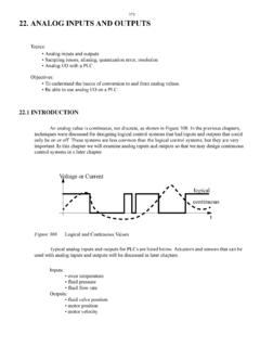
1 Techniques that Reduce System Noise in ADC Circuits By Bonnie C. Baker, Microchip Technology Inc. ANALOG DESIGN NOTE ADN007. It may seem that designing a low Noise , 12-bit Analog-to-Digital If this circuit is built without using low Noise precautions, Converter (ADC) board or even a 10-bit board is easy. This is it is very easy to produce an output similar to Figure 2. true, unless one ignores the basics of low Noise design. For Here, 1024 samples were taken at the output of the ADC. instance, one would think that most amplifiers and resistors work (MCP3201) at a data rate of 30 ksps.
2 These samples have effectively in 12-bit or 10-bit environments. However, poor device a 44 code spread centered around code 2982. From this selection becomes a major factor in the success or failure of the data, the System is approximately accurate. Clearly circuit. Another, often ignored, area that contributes a great deal this circuit is not good enough even for a 10-bit System . The of Noise , is conducted Noise . Conducted Noise is already in the specific configuration of this board is: circuit board by the time the signal arrives at the input of the ADC.
3 The most effective way to remove this Noise is by using a R3 = 300 k . low-pass (anti-aliasing) filter prior to the ADC. Including by-pass R4 = 100 k . capacitors and using a ground plane will also eliminate this type of Noise . A third source of Noise is radiated Noise . The major RG = 4020 . sources of this type of Noise are Electromagnetic Interference (EMI) or capacitive coupling of signals from trace-to-trace. A1 = A2 = single supply, CMOS op amp, MCP604. If all three of these issues are addressed, then it is true that No low-pass anti-aliasing filter included designing a low Noise 12-bit ADC board is easy.
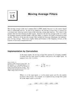
4 No by-pass capacitors included An example of a 12-bit circuit is shown in Figure 1. The signal No ground plane used originates at the resistive load cell, part number LCL-816-G. The differential output ports of the LCL-816-G are connected to a discrete, two-op-amp instrumentation amplifier (A1, A2, R3, R4. and RG). The signal then travels through a second order, low- pass filter (A3, R5, R6, C1 and C2). This low-pass filter eliminates unwanted, higher frequency Noise . Finally, the signal couples into a 12-bit ADC (A4, MCP3201). The converter is configured to accept signals from 0V to 5V.
5 The output of the converter is sent to the PIC16C623 microcontroller. VDD. Two-op-amp 12-bit Accurate Circuit Components Instrumentation Amplifier R3 = 30 k , R4 = 10 k , RG = 402 , ( 1%). R5 = k , R6 = 196 k , C1 = 100 nF, C2 = 470 nF. MCP3201 = 12-bit, A/D SAR Converter R3 RG. MCP6024 = Single Supply, CMOS, low Noise , quad op amp MCP1525. R4. Reference 2nd Order VDD = 5V. Low-Pass Filter VDD R3. VDD. _ C1. R1 R2 R4. 1/4 of _. MCP6024. R6. PIC16C623. 1/4 of R5 A4. + A1 + SCLK. MCP6024. R2 R1 1/41/4. of of DOUT. C2 MCP3201. + A2 MCP6024. MCP6024. LCL-816G CS.
6 _. A3. Figure 1. When you use low Noise devices, a ground plane, by-pass capacitors and a low-pass filter, it is possible to produce an accurate, 12-bit conversion every time. 2004 Microchip Technology, Inc. DS21854A - Page 1. It is easy to design a true 12-bit ADC System by using a few Code Width of Noise = 44 key low Noise guidelines. First, examine your devices (resistors (Total samples = 1024). and amplifiers) to make sure they are low Noise . Second, use a 90 ground plane whenever possible. Third, include a low-pass filter 80 in the signal path if you are changing the signal from analog to digital.
7 Finally, and always, include by-pass capacitors. These Number of Occurrences 70. capacitors not only remove Noise but also foster circuit stability. 60. 50. Code Width of Noise = 1. 40 (Total Samples = 1024). 30 1100. 20 1000. Number of Occurrences 10 900. 0 800. 700. 2960 2970 2980 2990 600. Output Code of 12-bit A/D Converter 500. 400. Figure 2. When low Noise precautions are not taken during circuit 300. design and board layout, a 12-bit ADC System under-performs with 200. approximately accuracy (or Effective Number of Bits). 100. 0. Modifying this circuit and board can result in a 12-bit 2940 2941 2942.
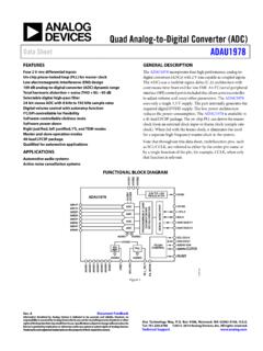
8 Accurate solution. As a first step, lower Noise devices Output Code of 12-bit A/D Converter are used. For instance, the resistors are made 10 times lower. When this is done, the gain remains the same, but the Noise is reduced by approximately 3 times. Figure 3. If low Noise , active and passive devices are used, a ground Additionally, the amplifiers are changed from the MCP604 plane is included, by-pass capacitors are added and a low-pass to the MCP6044. The MCP604's voltage Noise density, (anti-aliasing) filter is placed in the signal path. The code width of 1024.
9 Samples is equal to one. at 1 kHz, is 29 nV/ Hz (typ). The MCP6024's voltage Noise density, at 10 kHz, is nV/ Hz (typ). This is over 3 times improvement. As a third modification, a ground plane Recommended References: is added to the Printed Circuit Board (PCB). This ground plane is implemented so that interruptions in the metal are parallel AN681 - Reading and Using Fast Fourier Transforms (FFTs), instead of horizontal to the signal path. Baker, Bonnie C., Microchip Technology Inc. The performance of the board changes dramatically with these three modifications.
10 Tests show that the histogram output AN688 - Layout Tips for 12-Bit A/D Converter Application, of the ADC changes from a code width of 44 codes down to Baker, Bonnie C., Microchip Technology Inc. 9 codes. This dramatic change converts the circuit in Figure 1. into approximately a 9-bit System . AN695 - Interfacing Pressure Sensors to Microchip's Analog Peripherals, Baker, Bonnie C., This sounds good, but there is a 12-bit System to be found Microchip Technology Inc. in this application. Adding a second order filter (A3, R5, R6, C1 and C2), which is designed using the FilterLab software, AN699 - Anti-Aliasing, Analog Filters for Data Acquisition improves the performance.