Transcription of Tektronix: Primer > XYZs of Oscilloscopes
1 XYZs of of ContentsIntroduction ..3 Signal IntegrityThe Significance of Signal Integrity ..4 Why is Signal Integrity a Problem? ..4 Viewing the Analog Origins of Digital Signals ..5 The OscilloscopeUnderstanding Waveforms and Waveform Measurements ..6 Types of Waves ..7 Sine Waves ..7 Square and Rectangular Waves ..7 Sawtooth and Triangle Waves ..7 Step and Pulse Shapes ..8 Periodic and Non-periodic Signals ..8 Synchronous and Asynchronous Signals ..8 Complex Waves ..8 Waveform Measurements ..9 Frequency and Period ..9 Voltage ..9 Amplitude ..9 Phase ..10 Waveform Measurements with Digital Oscilloscopes ..10 The Types of OscilloscopesAnalog Oscilloscopes ..11 Digital Oscilloscopes ..12 Digital Storage Oscilloscopes ..13 Digital Phosphor Oscilloscopes ..15 Digital Sampling Oscilloscopes ..17 The Systems and Controls of an OscilloscopeVertical System and Controls ..18 Position and Volts per Division ..19 Input Coupling ..19 Bandwidth Limit.
2 20 Alternate and Chop Display Modes ..20 Horizontal System and Controls ..21 Acquisition Controls ..21 Acquisition Modes ..21 Starting and Stopping the Acquisition System ..23 Sampling ..23 Sampling Controls ..23 Sampling Methods ..23 Real-time Sampling ..24 Real-time Sampling with Interpolation ..25 Equivalent-time Sampling ..25 Random Equivalent-time Sampling ..26 Sequential Equivalent-time Sampling ..26 Position and Seconds per Division ..27 Time Base Selections ..27 Zoom ..27XY Mode ..27Z Axis ..27 XYZ Mode ..27 Trigger System and Controls ..28 Trigger Position ..29 Trigger Level and Slope ..30 Trigger Sources ..30 Trigger Modes ..30 Trigger Coupling ..30 Trigger Holdoff ..31 Display System and Controls ..31 Other Oscilloscope ControlsMath and Measurement Operations ..32 XYZs of Complete Measurement SystemProbes ..33 Passive Probes ..34 Active and Differential Probes ..35 Probe Accessories ..36 Performance Terms and ConsiderationsBandwidth.
3 37 Rise Time ..38 Sample Rate ..39 Waveform Capture Rate ..40 Record Length ..40 Triggering Capabilities ..41 Effective Bits ..41 Frequency Response ..41 Vertical Sensitivity ..41 Sweep Speed ..41 Gain Accuracy ..41 Horizontal Accuracy (Time Base) ..41 Vertical Resolution (Analog-to-digital Converter) ..41 Connectivity ..42 Expandability ..43 Ease-of-use ..44 Probes ..44 Operating the OscilloscopeSetting Up ..45 Ground the Oscilloscope ..45 Ground Yourself ..45 Setting the Controls ..46 Using Probes ..46 Connecting the Ground Clip ..46 Compensating the Probe ..47 Oscilloscope Measurement TechniquesVoltage Measurements ..48 Time and Frequency Measurements ..49 Pulse Width and Rise Time Measurements ..49 Phase Shift Measurements ..50 Other Measurement Techniques ..50 Written ExercisesPart IVocabulary Exercises ..51 Application Exercises ..52 Part IIVocabulary Exercises ..53 Application Exercises ..54 Answer Key ..55 Glossary ..56 XYZs of moves in the form of a sine wave, be it an ocean wave, earth-quake, sonic boom, explosion, sound through air, or the natural frequencyof a body in motion.
4 Energy, vibrating particles and other invisible forcespervade our physical universe. Even light part particle, part wave hasa fundamental frequency, which can be observed as can convert these forces into electrical signals that you canobserve and study with an oscilloscope. Oscilloscopes enable scientists,engineers, technicians, educators and others to see events that changeover are indispensable tools for anyone designing, manufacturingor repairing electronic equipment. In today s fast-paced world, engineersneed the best tools available to solve their measurement challenges quickly and accurately. As the eyes of the engineer, Oscilloscopes are the key to meeting today s demanding measurement usefulness of an oscilloscope is not limited to the world of the proper transducer, an oscilloscope can measure all kinds of phenomena. A transducer is a device that creates an electrical signal inresponse to physical stimuli, such as sound, mechanical stress, pressure,light, or heat.
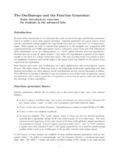
5 A microphone is a transducer that converts sound into anelectrical signal. Figure 1 shows an example of scientific data that can begathered by an are used by everyone from physicists to television repairtechnicians. An automotive engineer uses an oscilloscope to measureengine vibrations. A medical researcher uses an oscilloscope to measurebrain waves. The possibilities are concepts presented in this Primer will provide you with a good startingpoint in understanding oscilloscope basics and glossary in the back of this Primer will give you definitions of unfamiliar terms. The vocabulary and multiple-choice written exercises on oscilloscope theory and controls make this Primer a useful classroomaid. No mathematical or electronics knowledge is reading this Primer , you will be able to:Describe how Oscilloscopes workDescribe the differences between analog, digital storage, digital phosphor,and digital sampling oscilloscopesDescribe electrical waveform typesUnderstand basic oscilloscope controlsTake simple measurementsThe manual provided with your oscilloscope will give you more specificinformation about how to use the oscilloscope in your work.
6 Some oscilloscope manufacturers also provide a multitude of application notes to help you optimize the oscilloscope for your application-specific you need additional assistance, or have any comments or questions about the material in this Primer , simply contact your Tektronix representative, or visit of OscilloscopesPrimerPhoto CellLight SourceFigure example of scientific data gathered by an IntegrityThe Significance of Signal IntegrityThe key to any good oscilloscope system is its ability to accurately recon-struct a waveform referred to as signal integrity. An oscilloscope isanalogous to a camera that captures signal images that we can thenobserve and interpret. Two key issues lie at the heart of signal you take a picture, is it an accurate picture of what actually happened?Is the picture clear or fuzzy?How many of those accurate pictures can you take per second?Taken together, the different systems and performance capabilities of anoscilloscope contribute to its ability to deliver the highest signal integritypossible.
7 Probes also affect the signal integrity of a measurement integrity impacts many electronic design disciplines. But until a few years ago, it wasn t much of a problem for digital designers. Theycould rely on their logic designs to act like the Boolean circuits they , indeterminate signals were something that occurred in high-speeddesigns something for RF designers to worry about. Digital systemsswitched slowly and signals stabilized clock rates have since multiplied by orders of applications such as 3D graphics, video and server I/O demand vast bandwidth. Much of today s telecommunications equipment is digitally based, and similarly requires massive bandwidth. So too does digital high-definition TV. The current crop of microprocessor devices handles data at rates up to 2, 3 and even 5 GS/s (gigasamples persecond), while some memory devices use 400-MHz clocks as well as datasignals with 200-ps rise , speed increases have trickled down to the common IC devices used in automobiles, VCRs, and machine controllers, to name just a few applications.
8 A processor running at a 20-MHz clock rate may well have signals with rise times similar to those of an 800-MHzprocessor. Designers have crossed a performance threshold that means,in effect, almost every design is a high-speed some precautionary measures, high-speed problems can creep into otherwise conventional digital designs. If a circuit is experiencing intermittent failures, or if it encounters errors at voltage and temperature extremes, chances are there are some hidden signalintegrity problems. These can affect time-to-market, product reliability,EMI compliance, and is Signal Integrity a Problem?Let s look at some of the specific causes of signal degradation in today sdigital designs. Why are these problems so much more prevalent todaythan in years past?The answer is speed. In the slow old days, maintaining acceptable digital signal integrity meant paying attention to details like clock distribution, signal path design, noise margins, loading effects,transmission line effects, bus termination, decoupling and power distribution.
9 All of these rules still apply, Bus cycle times are up to a thousand times faster than they were 20 years ago! Transactions that once took microseconds are now measured in nanoseconds. To achieve this improvement, edge speeds too have accelerated: they are up to 100 times faster than those of two decades is all well and good; however, certain physical realities have kept circuit board technology from keeping up the pace. The propagation timeof inter-chip buses has remained almost unchanged over the have shrunk, certainly, but there is still a need to provide circuit board real estate for IC devices, connectors, passive components,and of course, the bus traces themselves. This real estate adds up to distance, and distance means time the enemy of s important to remember that the edge speed rise time of a digitalsignal can carry much higher frequency components than its repetitionrate might imply. For this reason, some designers deliberately seek ICdevices with relatively slow rise of lumped circuit model has always been the basis of most calculationsused to predict signal behavior in a circuit.
10 But when edge speeds aremore than four to six times faster than the signal path delay, the simplelumped model no longer board traces just six inches long become transmission lines when driven with signals exhibiting edge rates below four to six nanoseconds, irrespective of the cycle rate. In effect, new signal paths are created. These intangible connections aren t on the schematics, butnevertheless provide a means for signals to influence one another inunpredictable the same time, the intended signal paths don t work the way they are supposed to. Ground planes and power planes, like the signal traces described above, become inductive and act like transmission lines; power supply decoupling is far less effective. EMI goes up as faster edge speeds produce shorter wavelengths relative to the bus length. Crosstalk addition, fast edge speeds require generally higher currents to producethem. Higher currents tend to cause ground bounce, especially on widebuses in which many signals switch at once.