Transcription of Temperature Coefficient of Resistance for Current Sensing
1 V I S H AY D A L E. Resistors White Paper Temperature Coefficient of Resistance for Current Sensing By Bryan Yarborough HOW Temperature AND CONSTRUCTION AFFECT Resistance STABILITY. OBJECTIVE represent ppm/ C that may be easier to consider is that 1. What is TCR? 3900 ppm/ C is the same as %/ C. These may seem like small numbers until you consider the change in 2. How is TCR determined? Resistance due to a Temperature rise of 100 C. For copper 3. How does construction affect TCR performance? that would cause a 39 % change in Resistance . 4. TCR in applications An alternate method for visualizing the effect of TCR is to consider it in terms of the rate of expansion of a material with 5. How to compare datasheets Temperature . Consider two different bars, A and B, that are (1) each 100 m in length. Bar A changes length at a rate of CAUSE AND EFFECT. +500 ppm/ C and bar B changes length at a rate of Resistance is a result of a combination of factors that cause +20 ppm/ C.
2 A Temperature change of 145 C will cause the an electron's movement to deviate from an ideal path within length of bar A to increase m, whereas bar B will only a crystalline lattice of a metal or metal alloy. As an electron increase in length by m. Below is a scaled (1 / 20). encounters defects or imperfections within the lattice it can representation to visually demonstrate the difference. Bar A. cause diffusion. This increases the path traveled, resulting in has a very noticeable change in length, whereas bar B has an increased Resistance . These defects and imperfections no visible change in length. can result from: Bar A. Movement in the lattice due to thermal energy T = 25 C. Bar B. Different atoms present in the lattice, such as impurities Partial or complete absence of a lattice (amorphous Bar A. structure) T = 170 C. Bar B. Disordered zones at the grain boundaries Crystalline and interstitial defects in the lattice This also applies to a resistor in that the lower TCR will result in a more stable measurement across Temperature , which Note may be caused by applied power (causing the Resistance (1) Source: Zandman, Simon, & Szwarc Resistor theory and element Temperature to increase) or ambient environment.
3 Technology 2002 p. 23 - The Temperature Coefficient of Resistance (TCR), sometimes HOW TCR IS MEASURED. referred to as Resistance Temperature Coefficient (RTC), is a characteristic of the thermal energy component of the above TCR performance per MIL-STD-202 Method 304 is imperfections. The effect of this Resistance change is Resistance change based on a reference Temperature of reversible as the Temperature returns to reference 25 C. The Temperature is changed and the device under Temperature , assuming the grain structure was not altered test is allowed to reach equilibrium before the Resistance from high temperatures resulting from an extreme pulse / value is measured. The difference is used to determine the WHITE PAPER. overload event. For Power Metal Strip and Power Metal TCR. For the Power Metal Strip WSL model, the TCR is Plate products, this would be a Temperature that caused measured at the low Temperature of -65 C and then the Resistance alloy to exceed 350 C.
4 Measured at +170 C. The equation follows below. Typically This Resistance change due to Temperature is measured in an increase in Resistance with an increase in Temperature ppm/ C, which widely varies among different materials. For results in a positive TCR. Also, note that self-heating causes example, manganese-copper alloy has a TCR of a Resistance change due to TCR. < 20 ppm/ C (for 20 C to 60 C), whereas copper used in terminations is approximately 3900 ppm/ C. Another way to Revision: 11-May-2020 1 Document Number: 30405. For technical questions, contact: THIS DOCUMENT IS SUBJECT TO CHANGE WITHOUT NOTICE. THE PRODUCTS DESCRIBED HEREIN AND THIS DOCUMENT. ARE SUBJECT TO SPECIFIC DISCLAIMERS, SET FORTH AT White Paper Vishay Dale Temperature Coefficient of Resistance for Current Sensing Resistance - Temperature Coefficient (%): The operating Temperature (t2) is often based on the application. For example, the Temperature range for R2 R1 instrumentation is typically 0 C to 60 C, and -55 C to --------------------------------- 100 125 C is the typical range for military applications.
5 The R 1 ( t2 t1 ). Power Metal Strip WSL series provides TCR for its operating Resistance - Temperature Coefficient (ppm): range of -65 C to +170 C, while the WSLT series has an extended Temperature range to 275 C. R2 R1. --------------------------------- 1 000 000 The table below gives the TCR for some Resistance materials R1 ( t2 t1 ) used in the range of products in this brochure. R1 = Resistance at reference Temperature R2 = Resistance at operating Temperature t1 = reference Temperature (25 C). t2 = operating Temperature TCR, ppm/ C OF VARIOUS RESISTOR ELEMENT MATERIALS. Temperature range -55 C to +25 C 0 C to +25 C +25 C to +60 C +25 C to +125 C. Manganin +50 +10 -5 -80. Zeranin +20 +10. Evanohm + + Foil + + Thin film -10 + +10. Thick film -100 -25 +50 +100. The following graph compares different TCR levels as a percentage change in Resistance versus increasing Temperature from 25 C. TCR Error (over Temperature range). %. %. Change in Resistance (%).
6 %. % 500 ppm 100 ppm % % %. % % 20 ppm 10 ppm 0 ppm (ideal). 25 50 75 100 125. Temperature ( C). The following equation calculates the maximum change in Resistance value for a given TCR. R = R0 [ 1 + ( T T0 ) ]. WHITE PAPER. R = final Resistance R0 = initial Resistance = TCR. T = final Temperature T0 = initial Temperature Vishay offers an online TCR calculator at Revision: 11-May-2020 2 Document Number: 30405. For technical questions, contact: THIS DOCUMENT IS SUBJECT TO CHANGE WITHOUT NOTICE. THE PRODUCTS DESCRIBED HEREIN AND THIS DOCUMENT. ARE SUBJECT TO SPECIFIC DISCLAIMERS, SET FORTH AT White Paper Vishay Dale Temperature Coefficient of Resistance for Current Sensing HOW CONSTRUCTION AFFECTS TCR copper terminal and the low TCR Resistance alloy. For the The Power Metal Strip and Power Metal Plate series offer lowest Resistance values of a specific resistor construction, superior TCR performance when compared to traditional the copper becomes more significant in the TCR rating and all-metal thick film Current sense resistors.
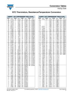
7 A thick film performance. Current sense resistor utilizes a material that is primarily silver, with terminals of silver and copper. Silver and copper have similarly large TCR performance values. For a video Total Total walkthrough comparing TCR technologies, refer to Resistance Resistance 10 m: 1 m: Switching Voltage at 400 mA. V This influence may occur at different Resistance value ranges for different parts. For example, the TCR rating of the V. WSLP2512 is 275 ppm/ C at 1 m , while the WSLF2512 is V 170 ppm/ C at 1 m . The WSLF has a lower TCR because the copper terminal has a lower Resistance contribution for V Thick Film the same Resistance value. Typical V Metal Strip Vishay Power KELVIN TERMINAL VS. 2 TERMINAL. Metal Strip The Kelvin (4 terminal) construction provides two benefits: 25 C 50 C 70 C. Temperature improved Current measurement repeatability and improved TCR performance. The notched construction reduces the The Power Metal Strip resistor series uses a solid copper amount of in-circuit copper from the measurement.
8 The terminal (item 2 in the illustration) that is electron beam table below illustrates the benefits of a Kelvin-terminated welded to a low TCR Resistance alloy (item 1), achieving low WSK2512 compared to the 2-terminal WSLP2512. values down to m with low TCR. However, the copper terminal has a high TCR (3900 ppm/ C) compared to the Resistance RANGE (m ) WSLP2512 WSK2512. Resistance alloy (< 20 ppm/ C), which still plays a role in the 400 350. overall TCR performance as lower Resistance values are required. 1 275 250. 3 150 75. 5 200 75 35. There are two key questions (example graphic is of the WSL3637). Why not notch all the way to the Resistance alloy for 4 the best TCR? 1 This would introduce a new problem because the copper 3. 2. allows for a low resistivity connection to the region of 1. Resistive element 2. Copper terminal with solderable finish Current flow to be measured. Notching all the way to the 3. Terminal to element weld Resistance alloy would cause the measurement to be 4.
9 High Temperature encapsulent applied through a portion of the Resistance alloy where The copper terminal provides a low Resistance connection to there is no Current flow. This would result in an increased the Resistance alloy, which enables a uniform distribution of measured voltage. It is a compromise between copper Current flow to the Resistance element for a more accurate TCR effects and measurement accuracy and repeatability WHITE PAPER. Current measurement for high Current applications. Can I use a 4-terminal pad design to obtain the same However, the copper terminal has a high TCR results? (3900 ppm/ C) as compared to the Resistance alloy No. While the 4-terminal pad design does offer better (< 20 ppm/ C), which has a significant impact on the overall measurement repeatability, it does not remove the effects TCR performance at very low Resistance values. This is of copper from the measurement circuit. The resistor will portrayed in the following graphic demonstrating how the still perform to the same rated TCR.
10 Total Resistance is influenced by the combination of the Revision: 11-May-2020 3 Document Number: 30405. For technical questions, contact: THIS DOCUMENT IS SUBJECT TO CHANGE WITHOUT NOTICE. THE PRODUCTS DESCRIBED HEREIN AND THIS DOCUMENT. ARE SUBJECT TO SPECIFIC DISCLAIMERS, SET FORTH AT White Paper Vishay Dale Temperature Coefficient of Resistance for Current Sensing TCR IN AN APPLICATION (AMBIENT AND. APPLIED POWER). ge lta Vo nse While TCR is typically considered in terms of how the ed se resistor changes based on environmental or ambient p pli nt A rr e cu conditions, there is another dimension to consider;. Temperature rise due to applied power. When power is applied the resistor heats due to converting electrical energy to thermal energy. This Temperature increase due to applied power is also a component related to TCR, sometimes referred to as power Coefficient of Resistance (PCR). PCR introduces another layer that is driven by construction, which is based on thermal conduction through the part or internal thermal Resistance , Rthi.