Transcription of TEMPERATURE CONTROLLER OPERATION MANUAL
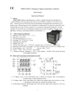
1 TEMPERATURE CONTROLLER . OPERATION MANUAL . TB100 TB400 TB700 TB600 TB900. Before using please check whether range , input and output match your requirement. 1. Front panel instruction DISPLAY. PV Process value 4 digit display (red color). SV Setting value 4 digit display (green color). LED. OUT1 Output 1 green color OUT2 Output 2 green color AT Auto Tuning yellow color PRO Program yellow color --- Only available for PTB models. AL1 Alarm 1 red color AL2 Alarm 2 red color MAN MANUAL yellow color KEY. SET MODE SET key SHIFT key DOWN key UP key A/M Auto/ MANUAL key 2 Auto tuning Once AT set YES auto tuning is to be performed. After auto tuning finished PID parameter is to be set auomatically. ATVL=auto tuning offset and it will be deduced from SV. (it can prevent over shoot during auto tuning). SV-ATVL=Auto-tuning value ATVL=auto tuning offset ATVL=5 Auto tuning point is at 195.
2 ATVL means Auto-tuning point in program type Auto tuning failure Passible 1 ATVL is too big. (If not sure set ATVL=0). Passible 2 System time is too long.(Set PID parameter individually). 1. 3. Error information DISPLAY DESCRIPTION. IN1E Open circuit of main control sensor. ADCF A/D converter failed. CJCE Cold junction compensation failed. IN2E Open circuit of sub control sensor. UUU1 PV exceeds USPL. NNN1 PV under LSPL. UUU2 Input signal of sub control exceeds the upper limit. NNN2 Input signal of sub control under the lower limit. RAMF RAM failed. INTF Interface failed. AUTF Auto tuning failed. If the marked error comes up the CONTROLLER needs repair. NOTE . Please send it to the nearest sales office or retail dealer. 2. 4. Operating flow LEVEL 1 (User Level). Display PV PV. Display SV SV. set To LEVEL 2. (press Set key for 5 sec.). Output Percentage OUTL.
3 100. set Auto Tuning Status AT. YES/NO. set Alarm 1 set AL1. 0. set Alarm 2 set AL2. 0. set Alarm 3 set AL3. 0. Press the SHIFT KEY ( ) to change the parameters. If the SHIFT. KEY is pressed the first digit begins blinking. Press the UP KEY( ). or DOWN KEY( ) to increase or decrease the value of the digit . then press the SHIFT KEY( ) again to go to the next digit. As all the digit are written press SET KEY to enter the value. SET KEY also has the function of changing MODEs if the SET KEY. is pressed the display shows the next MODE. Press SET KEY for 5 sec. the display goes to LEVEL 2 and do the same thing to return LEVEL 1. If any key were not pressed for 1 minute the display would go to LEVEL 1. Press A/M KEY the display to go to LEVEL 1 no matter where it is. If OUTL set "0" it means the CONTROLLER has no output, 3. LEVEL 2 (PID Level). press SET key for 5 seconds to enter Level 2.
4 P1 Main Control Range 0-200%. 3 Proportional Band ON/OFF at P=0. Set I1 Main Control Range 0~3600 Sec 240 Integral Time Integral OFF at I=0. Set D1 Main Control Range 0~900 Sec 60 Derivative Time Derivative OFF at D=0. Set db 1 Main Control Dead time compensation 0 Dead-band Time Range 0~1000 Sec Set ATVL Main Control 0 Range 0~USPL. Auto tuning off-set Set Output (SSR=1 4 ~ 20mA=0 Relay=over CYT1 Main Control 10). 10 Proportional Cycle Range 0~150 Sec Set HYS1 Main Control For ON/OFF control only 1 Hysteresis Range 0~1000. Set P2 Sub Control 3 Sames as P1. Proportional Band Set I2 Sub Control 240 Sames as I1. Integral Time Set D2 Sub Control 240 Sames as D1. Derivative Time Set CYT2 Sub Control 10 Sames as CYT1. Proportional Cycle Set HYS2 Sub Control 1 Sames as HYS1. Hysteresis Set GAP1 Main Control For 2 output use only set the volume turning. 0 Gap (Output 1) "OFF" early to SV.
5 Set GAP2 Sub Control For 2 output use only set the volume turning. 0 Gap (Output 2) "ON" early to SV. Set LCK Function Lock 0000. Set LCK=0000. 0000 To 0000 enter any Level ( not include SET Level) and change their parameters Return P1 LCK=1111. 1111 To 1111 enter any Level (include SET Level) and change their parameters LCK=0100. 0100 To 0100 enter Level 1 & 2 and to change their parameters. LCK=0110. 0110 To 0110 enter Level 1 & 2 and to change Level 1parameters only. LCK=0001. 0001 To 0001 enter Level 1 only and to change SV only. LCK=0101. 0101 it 0101 can't change any parameter except LCK. 4. LEVEL 3 (INPUT Level). When LCK=0000 press SET key and SHIFT KEY for 5 seconds to enter LEVEL 3. INP1 Main Control select the input range refer to input K2 input selection selection ( ~ 13). Set ANL1 Main Control It is used as input code are AN1 to AN5. 0 Analog Zero set Range LSPL~USPL.
6 Set ANH1 Main Control 5000 Same as ANL1. Analog Span set Set DP Decimal point To set the position of decimal point 0000. Set LSPL Lower set-point limit To set the lowest point within INP1. Set USPL Upper set-point limit To set the highest point within INP1. Set ANL2 Sub Control It is used as input code are AN1 to AN5. 0 Analog Zero set Range LSPL~USPL. Set ANH2 Sub Control 5000 Sames as ANL2. Analog Span set Set ALD1 Alarm mode of AL1 Range:00~19 (see ~15). 01. Set It is used in program function ALT1 Time set of Alarm 1 Range 0~ min. 0=flicker alarm . 10. Set and other=on delay time ALD2 Alarm mode of AL2 Range:00~19 (see ~15). 01. Set ALT2 Time set of Alarm 2 Sames as ALT1. 0. Set ALD3 Alarm mode of AL3 Range:00~19 (see ~15). 01. Set ALT3 Alarm 3 time set Sames as ALT1. 0. Set HYSA Hysteresis of alarm Range 0~1000. 0. Set CLO1 Main Control Calibrate the low value of output 150 calibration Range LSPL~USPL(current output only).
7 Set 5. CHO1 Main Control To calibrate the high value of output 3500 Calibration high Range:0~9999(current output only). Set CLO2 Sub control 150 Same as CLO1. Calibration low Set CHO2 Sub control 3200 Same as CHO1. Calibration high Set CLO3 Transmitter control Same as CLO1. Calibration low Set CHO3 Transmitter control Same as CHO1. Calibration high Set RUCY Full run time of proportional motor 00 Timer of motor (without potentiometer) Range 0~150 sec. Set Use in program for WAIT waiting continued 0=No Wait 0 OPERATION Other=Wait volume Set HYSM Hysteresis for motor 1 Range 0~1000. control Set IDNO ID number 1 Communication ID number (don't care). Set BAUD Baud rate UART baud rate selection 2400 (don't care) Range 110~9600 BIT/sec Set SVOS Compensate SV Range -1000~1000. 0. Set PVOS Compensate PV Range LSPL~USPL. 0. Set UNIT Unit of PV & SV Range C F A(analog).
8 C. Set Adjust the response time of PV. SOFT Soft filter 1000 (the bigger the faster). (don't care). Set Range ~ CASC don't care Set OUD Action mode Range heat cool HEAT. Set OPAD Control action Range PID Fuzzy PID. Set HZ Frequency Range 50 60HZ. 60. Set Return INP1. 6. LEVEL 4 (SET Level). When LCK=1111 press SET key and SHIFT KEY for 5 seconds to enter Level 4. There are SET to SET for use.. Display . Press SET key to change SET 1 SET 0.* ~ 9.*. 0=lock 0 1 0 1 1=open SET * . 1. SET * . 2. SET * . 3. SET * . 4. Function of SETs SET Function SET Function OUTL CLO2 CHO2. AT CLO3 CHO3. AL1 RUCY WAIT HYSM. AL2 IDNO BAUD. AL3 SVOS. ANL1 ANH1 DP PVOS. LSPL USPL UNIT. ANL2 ANH2 SOFT. ALD1 CASC. ALT1 OUD. ALD2 OPAD. ALT2 HZ. ALD3. ALT3. HYSA. CLO1 CHO1. 7. SET Function Remarks 0=No repeat 1=Program repeat 0=No power failure Program Use 1=With power failure 0=Start from 0.
9 1=Start from PV. TRS SV Auxiliary Output Use TRS PV. 0=No Remote SV. 1=Remote SV. ! Please don't operate SET otherwise the CONTROLLER 's process NOTE . will be in confusion. FUNCTION OF LCK. LCK=0000 It can enter Level 3 ( press SET + for 5 sec.). LCK=1111 It can enter Level 4 ( press SET + for 5 sec.). LCK=0100 It can enter Level 1 & 2 and change their parameters. LCK=0110 It can enter Level 1 & 2 but change Level 1 parameters only. LCK=0001 It can enter Level 1 only and change SV only. LCK=0101 It can't change any parameters except LCK. 8. PROGRAM LEVEL (to be ordered). LEVEL 1. Set PTN Set program pattern SV-5. 1 Set volume for Range 0~2. Set Set SEG Program segment display TM-5 Set time for 1 Resprent ("pattern"_"segment"). Set Set Program timer display TIMER Range 0~99 hour 59 OUT-5 Set output for Set min Set Set volume for SV-1 Range SV-6 Set volume for Set LSPL~USPL Set TM-1 Set time for TM-6 Set time for Range 0~99 hour 59 min Set Set Set output for OUT-1 Range 0~100%.
10 OUT-6 Set output for 100 If OUT=0 No program function Set Set SV-2 Set volume for SV-7 Set volume for Set Set TM-2 Set time for TM-7 Set time for Set Set OUT-2 Set output for OUT-7 Set output for Set Set SV-3 Set volume for SV-8 Set volume for Set Set TM-3 Set time for TM-8 Set time for Set Set OUT-3 Set output for OUT-8 Set output for Set Set SV-4 Set volume for Return LEVEL 1. Set TM-4 Set time for Set OUT-4 Set output for Set 9. This program has 2 patterns each pattern contains 8 segments. The segment can be arranged a period of Ramp status or Soak status. Terminologies pattern A program consists of some steps. Step A Ramp status + a Soak status. Ramp status The status with changing SV. Ramp status The status with fixed SV. Operating 1. "KEY" function(no changing parameter). (START) To start program procedure PRO in panel flicker. (WAIT) To suspend program procedure PRO in panel will stop flicker but light.