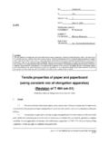
Transcription of Tensile Strength, Elongation, and Modulus - IPC
1 ScopeThis test method establishes a procedure fordetermining the Tensile strength , elongation and Young smodulus of organic free Applicable DocumentsASTM D 618 Standard Practice for Conditioning Plastics andElectrical Insulating Materials for TestingASTM D 882 Standard Test Methods for Tensile Propertiesof Thin Plastic SheetingASTM D 1005 Standard Test Methods for Measurement ofDry-Film Thickness of Organic Coatings Using MicrometersASTM D 2370 Standard Test Method for Tensile Propertiesof Organic Test SpecimenThe test specimen shall consist of astrip mm wide by mm in length and at least 10 m in thickness. The width of the specimen should not devi-ate by more than 2% over the length of the specimenbetween the grips.
2 The thickness of the films shall not vary bymore than 10% over the entire film. A minimum of ten speci-mens are Apparatus or Thickness Measurement DeviceMitutoyo 519-605 Mini-Checker with a 519-891 probe with vacuum assist con-nected to a MUX-10 multiplexer or equivalent thickness mea-surement device accurate and precise to Width Measurement DeviceMicrometer or equivalentwidth measurement device capable of measuring to Specimen CutterThwing-Albert JDC Precision Cutteror equivalent. The specimen cutting device must be capableof cutting a film strip mm wide over the length ofthe specimen. It is imperative that the cutting edges be keptsharp and free from visible scratches or nicks.
3 The use ofstriking dies is not recommended because of poor and incon-sistent specimen Tensile TesterInstron Model 4501 Tensile Tester witha kN load cell or equivalent. The testing machine must beequipped with a load cell whose compliance is a maximum of2% of the specimen extension within the range being mea-sured. Digital (as opposed to analog) self-calibrating load cellsare preferred since they eliminate the need for and potentialerror associated with calibrating analog load cells using exter-nal weights. The testing machine must be equipped with adevice for recording the Tensile load and the amount of sepa-ration of the grips; both of these measuring systems shouldbe accurate to 2%.
4 The rate of separation of the grips shallbe accurate to and capable of adjustment fromapproximately 0 to 50 Gripping DevicesA gripping system that minimizesboth slippage and uneven stress distribution must be grips must be self-aligning, they must be attached insuch a manner that they will move freely into alignment assoon as any load is applied so that the long axis of the speci-men will coincide with the direction of the applied pull throughthe center line of the grip Grip FacesSpecimen slippage and necking of thespecimen up into the grips are two of the most commonproblems with this test method. Slippage can be checked bydrawing a series of parallel lines across the part of the speci-men in the grips.
5 After pulling the specimen, if the lines are notparallel, the specimen may be slipping on one side. On speci-mens with high elongations, necking of the specimen into thegrips is a problem. As the specimen elongates, the reductionof area (necking) results in a loosening of the specimen at theinside edges of the grips. This loosening propagates furtherback into the grips with continued elongation of the can lead to erroneous results for the elongation . Air-actuated grips lined with rubber faces ( , neoprene) thathave been machined flat were found to be effective againstboth of these problems and still allowed the specimen to beeasily removed from the grips after the test.
6 Another approachis to use line grips, grips having faces designed to concen-trate the entire gripping force along a single line the width ofthe specimen perpendicular to the direction of the testingstress. This is usually done by combining one standard flatgrip face and an opposing grip face that has been cut cases where specimens frequently fail at the edge of thegrips, it may be advantageous to round the edges of the gripfaces where they meet the test area of the Institute for Interconnecting and Packaging Electronic Circuits2215 Sanders Road Northbrook, IL 60062-6135 IPC-TM-650 TEST METHODS strength , elongation , and ModulusDate7/95 RevisionOriginating Task GroupDeposited Dielectric Task Group (C-13a)Material in this Test Methods Manual was voluntarily established by Technical Committees of the IPC.
7 This material is advisory onlyand its use or adaptation is entirely voluntary. IPC disclaims all liability of any kind as to the use, application, or adaptation of thismaterial. Users are also wholly responsible for protecting themselves against all claims or liabilities for patent referenced is for the convenience of the user and does not imply endorsement by the Extension Indicators (optional)Extension indicators( , extensometers) must be designed as to minimize stresson the specimen at the contact points of the specimen andthe indicator. Clip type extensometers are not recommendedfor this reason. Laser extensometers can be used if themethod of marking the specimen does not induce any stressor strain into the specimen ( , scratching the specimen) orchange the specimen in any fashion ( , heating thespecimen).
8 CalibrationThe thickness gauge should be calibratedevery six months using standard gauge blocks. The blades onthe film cutter should be resharpened or replaced at leastonce a year. The load cell on the Tensile tester should be cali-brated at least once a week following the manufacturer s rec-ommended procedure. Also, the stops which control the ini-tial grip separation should be checked once a Operating ConditionsThe tests should be conductedat 23 2 C and 50 5% relative Preparation of Test test specimens should be conditioned at 23 2 C and 50 5% relative humidity for not less than 24 hoursprior to testing. Refer to ASTM D free films are placed between two cover sheets ofclear film (MylarT* or equivalent) to facilitate handling of at least 10 specimens mm long and wide.
9 No specimen shall vary by more than 2% in widthalong its entire length. The utmost care must be exercised incutting specimens to prevent nicks and tears along the edgesof the specimen that are likely to cause premature failure. Ifthe properties in the plane of the film are not isotropic ( ,the films were not prepared by spin coating), then ten filmsmust be cut in both the machine direction (MD) and transversedirection (TD). and record the thickness of the test speci-men to an accuracy of m at no fewer than five differentplaces within the gauge length area. Refer to ASTM D 1005and AST D the initial gauge length (grip separation) at and the rate of grip separation at the specimen in the grips of the testingmachine, taking care to align the long axis of the specimenwith an imaginary line joining the points of attachment of thegrips to the machine.
10 The specimen should be aligned as per-fectly as possible with the direction of pull so that no rotarymotion that may induce slippage will occur in the the grips evenly and firmly to the degree necessary tominimize slipping of the specimen during testing. The use ofair activated grips facilitates the mounting of the specimen inthe the test and record the load versus steps - for each series of each series of ten specimens, the arithmetic meanand standard deviation of each property for the specimenswith the five highest Tensile strengths shall be calculated to theproper number of significant figures. This is done on the basisthat the expected errors (nicks or flaws in the specimen,breaks within the grips, specimen slippage, etc.)