Transcription of TH8320U and TH8321U Touch Screen Programmable …
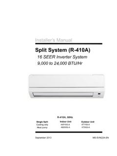
1 Registered TrademarkCopyright 2004 Honeywell International Inc. All Rights Reserved INSTALLATION INSTRUCTIONS69-1706TH8320U and TH8321U Touch ScreenProgrammable ThermostatsAPPLICATIONThe TH8320U and TH8321U Touch Screen Universal Programmable Thermostats provide electronic control of 24 Vac heating and cooling systems or 750 mV heating system. See Table 1 for a general NOTICEIf this control is replacing a control that contains mercury in a sealed tube, do not place your old control in the trash. Dispose of your local waste management authority for instructions regarding recycling and the proper disposal of the old Installing this these instructions carefully. Failure to follow the instructions can damage the product or cause a hazardous the ratings given in the instructions to make sure the product is suitable for your must be a trained, experienced service completing installation, use these instructions to check out the product LocationInstall the thermostat about 5 ft.
2 ( ) above the floor in an area with good air circulation at average temperature. See Fig. 1. Fig. 1. Selecting thermostat 1. TH832 Thermostats MethodChangeoverSystem SelectionFan SelectionCommentsTH8320 UBatteries or common wireAutomatic or manual selectableHeat-Off-Cool-Auto (Em. Heat for heat pumps)On-Auto-CircSystem and Fan selection vary based on system typeTH8321 USystem and Fan selection vary based on System type. Humidity sensor to control FEET[ METERS]YESNONONOM19925TH8320U AND TH8321U Touch Screen Programmable THERMOSTATS69-17062Do not install the thermostat where it can be affected by: Drafts or dead spots behind doors and in corners. Hot or cold air from ducts. Radiant heat from sun or appliances. concealed pipes and chimneys.
3 Unheated (uncooled) areas such as an outside wall behind the WallplateCAUTIONE lectrical cause electrical shock or equipment power before thermostat can be mounted horizontally on the wall or on a 4 in. x 2 in. ( mm x mm) wiring and level the wallplate (for appearance only). a pencil to mark the mounting 2. Mounting the wallplate from the wall and, if drywall, drill two 3/16-in. holes in the wall, as marked. For firmer material such as plaster, drill two 7/32-in. holes. Gently tap anchors (provided) into the drilled holes until flush with the the wallplate over the holes, pulling wires through the wiring opening. See Fig. the mounting screws into the holes and (FIG. 5-16)All wiring must comply with local electrical codes and ordinances.
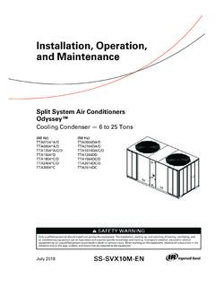
4 Set of terminal identifications (Table 2) that corresponds with system type (conventional or heat pump in Fig. 3). the screws for the appropriate system type selected; see Table 2. Insert wires in the terminal block under the loosened screw. See Fig. tighten each excess wire back into the the hole with nonflammable insulation to prevent drafts from affecting the 3. Selecting terminal identifications for system 4. Inserting wires in terminal Use 18 gauge thermostat HOLES (2)M19916 MOUNTING SCREWS (2)WALL ANCHORS (2)WIRES THROUGH WALLAND WIRE SLOTT able 2. Selecting Terminal Identifications for System TypeWallplate Terminal Identifications wiring Diagram ReferenceStandard Heat/CoolConventional5, 6 Heat OnlyConventional7 Heat Only with FanConventional8 Heat Only Series 20 Conventional9 Cool OnlyConventional10 Standard Multistage up to 2 Heat/2 CoolConventional11, 12 Heat Pump with No Auxiliary HeatHeat Pump13, 14 Heat Pump with Auxiliary HeatHeat Pump15, 16 CONVENTIONALSCREW TERMINALSHEAT PUMPM19951Y2 LEAUXS1S2Y2W2S1S2 RCRO/BYGCRCRWYGCM19917TH8320U AND TH8321U Touch Screen Programmable THERMOSTATS369-1706 Fig.
5 5. Typical hookup of conventional single-stage heat and cool system with single transformer (1H/1C conventional).Fig. 6. Typical hookup of conventional single-stage heat and cool system with two transformers (1H/1C conventional).Fig. 7. Typical hookup of heat-only system (1H conventional).Fig. 8. Typical hookup of heat only system with fan (1H conventional).COMPRESSORCONTACTORM19895 OUTDOOR/INDOORTEMPERATURESENSORHEAT RELAYFANRELAYRCPOWER SUPPLY. PROVIDE DISCONNECT MEANS AND OVERLOAD PROTECTION AS REQUIRED. FACTORY INSTALLED OUTDOOR OR INDOOR REMOTE SENSOR. AVAILABLE ON SELECT MODELS. WIRES MUST HAVE A CABLE SEPARATE FROM THE THERMOSTAT VAC COMMONCONNECTIONY2 RCS1RS2WW2 YGC2 CONVENTIONALCR1 COMPRESSORCONTACTORM19896 OUTDOOR/INDOORTEMPERATURESENSORHEAT RELAYFANRELAYRCPOWER SUPPLY.
6 PROVIDE DISCONNECT MEANS AND OVERLOAD PROTECTION AS REQUIRED. REMOVE FACTORY INSTALLED OUTDOOR OR INDOOR REMOTE SENSOR. AVAILABLE ON SELECT MODELS. WIRES MUST HAVE A CABLE SEPARATE FROM THE THERMOSTAT VAC COMMONCONNECTIONY2 RCS1RS2WW2 YGC2 CONVENTIONALM19897 OUTDOOR/INDOORTEMPERATURESENSORHEAT RELAYRCPOWER SUPPLY. PROVIDE DISCONNECT MEANS AND OVERLOAD PROTECTION AS REQUIRED. FACTORY INSTALLED OUTDOOR OR INDOOR REMOTE SENSOR. AVAILABLE ON SELECT MODELS. WIRES MUST HAVE A CABLE SEPARATE FROM THE THERMOSTAT VAC COMMONCONNECTIONY2 RCS1RS2WW2 YGC2 CONVENTIONALM19898 OUTDOOR/INDOORTEMPERATURESENSORHEAT RELAYFANRELAYRCPOWER SUPPLY. PROVIDE DISCONNECT MEANS AND OVERLOAD PROTECTION AS REQUIRED. FACTORY INSTALLED OUTDOOR OR INDOOR REMOTE SENSOR.
7 AVAILABLE ON SELECT MODELS. WIRES MUST HAVE A CABLE SEPARATE FROM THE THERMOSTAT VAC COMMONCONNECTIONY2 RCS1RS2WW2 YGC2 CONVENTIONALTH8320U AND TH8321U Touch Screen Programmable THERMOSTATS69-17064 Fig. 9. Typical hookup of heat only Series 20 10. Typical hookup of cool only system (1C conventional).Fig. 11. Typical hookup of conventional multistage two-stage heating and two-stage cooling in a single transformer system (2H/2C or 2H/1C or 1H/2C conventional).M19899 OUTDOOR/INDOORTEMPERATURESENSORPOWER SUPPLY. PROVIDE DISCONNECT MEANS AND OVERLOAD PROTECTION AS REQUIRED. FACTORY INSTALLED OUTDOOR OR INDOOR REMOTE SENSOR. AVAILABLE ON SELECT MODELS. WIRES MUST HAVE A CABLE SEPARATE FROM THE THERMOSTAT 20 MOTOR ORVALVEM19900 OUTDOOR/INDOORTEMPERATURESENSORFANRELAYR CPOWER SUPPLY.
8 PROVIDE DISCONNECT MEANS AND OVERLOAD PROTECTION AS REQUIRED. FACTORY INSTALLED OUTDOOR OR INDOOR REMOTE SENSOR. AVAILABLE ON SELECT MODELS. WIRES MUST HAVE A CABLE SEPARATE FROM THE THERMOSTAT VAC COMMONCONNECTIONY2 RCS1RS2WW2 YGC2 CONVENTIONALCOMPRESSORCONTACTORRCRWYGCY2 W2S2S1 CONVENTIONALCOOL RELAY 2 COOL RELAY 1M19901 HEAT RELAY 1 FAN RELAYHEAT RELAY 2 RCPOWER SUPPLY. PROVIDE DISCONNECT MEANS AND OVERLOAD PROTECTION AS REQUIRED. 11223 FACTORY INSTALLED OUTDOOR OR INDOOR REMOTE SENSOR. AVAILABLE ON SELECT MODELS. WIRES MUST HAVE A CABLE SEPARATE FROM THE THERMOSTAT 24 VACCOMMON CONNECTIONMUST COME FROMTHE AND TH8321U Touch Screen Programmable THERMOSTATS569-1706 Fig. 12. Typical hookup of conventional multistage two-stage heating and two-stage cooling in a two-transformer system (2H/2C or 2H/1C or 1H/2C conventional).
9 Fig. 13. Typical hookup of single-stage heat pump with no auxiliary/backup heat (1H/1C heat pump).RCRWYGCY2W2S2S1 CONVENTIONALCOOL RELAY 2 COOL RELAY 1M19902 HEAT RELAY 1 FAN RELAYHEAT RELAY 2 RCPOWER SUPPLY. PROVIDE DISCONNECT MEANS AND OVERLOAD PROTECTION AS REQUIRED. 11RC1223 FACTORY INSTALLED JUMPER OUTDOOR OR INDOOR REMOTE SENSOR. AVAILABLE ON SELECT MODELS. WIRES MUST HAVE A CABLSEPARATE FROM THE THERMOSTAT 24 VACCOMMON CONNECTIONMUST COME FROMTHE PUMPCOMPRESSORM19903 CHANGEOVERVALVEFAN RELAYRC112234334 OPTIONAL 24 VACCOMMON CONNECTIONPOWER SUPPLY. PROVIDE DISCONNECT MEANS AND OVERLOAD PROTECTION AS REQUIRED. FACTORY INSTALLED JUMPER."O/B" TERMINAL SET TO CONTROL AS EITHER "O" OR "B" IN THE INSTALLER OUTDOOR OR INDOOR REMOTE SENSOR. AVAILABLE ON SELECT MODELS.
10 WIRES MUST HAVE A CABLE SEPARATE FROM THE THERMOSTAT AND TH8321U Touch Screen Programmable THERMOSTATS69-17066 Fig. 14. Typical hookup of multistage heat pump with no auxiliary/backup heat (2H/2C heat pump).Fig. 15. Typical hookup of single-stage heat pump with auxiliary/backup heat (2H/1C heat pump).RCRO/BYGCY2 LEAUXSIS2 HEAT PUMPCOMPRESSOR 1 COMPRESSOR 2M19904 CHANGEOVERVALVEFAN RELAYRC112234554433 OPTIONAL 24 VACCOMMON CONNECTIONPOWER SUPPLY. PROVIDE DISCONNECT MEANS AND OVERLOAD PROTECTION AS REQUIRED. FACTORY INSTALLED CONNECT THE 24 VAC COMMON WHEN USING L. THE TERMINAL IS SHOWN AS EQUIPMENT MONITOR, CAN ALSO BE USED AS A 24 VAC OUTPUT. SEE "L TERMINAL" SECTION FOR MORE INFORMATION."O/B" TERMINAL SET TO CONTROL AS EITHER "O" OR "B" IN THE INSTALLER OUTDOOR OR INDOOR REMOTE SENSOR.