Transcription of THE AERODYNAMIC DESI GN OF THE A350 XWB-900 HIGH …
1 1 Abstract The A350 XWB-900 is the first member of the new family of Airbus long range high-lift aircraft . The development was launched in 2006 and the first aircraft performed its maiden flight in June 2013. Shaping Efficiency was the directive for the design of the aircraft , which was valid for all involved disciplines but of special motivation for aerodynamics. That means for the high-lift system to deliver maximum AERODYNAMIC efficiency for low approach speeds and low take off drag, while keeping the overall system small and simple to provide low weight and low complexity. 1 Design History In spring 2006 Airbus decided to stop the development of the initial A350, which was based on the A330 in order to offer the customers an all-new aircraft with even better performance, higher cruise Mach number and AERODYNAMIC efficiency (L/D).
2 The new clean-sheet design was named A350 XWB, where Extra Wide Body (XWB) referred to the modified fuselage cross-section. The new design should provide a 25% reduction in fuel efficiency compared to its current long range competitors. This was achieved with a new wing layout with more wing sweep allowing for a cruise Mach-number of The highly tapered inboard loaded wing is optimized for AERODYNAMIC cruise efficiency and low structural weight. It has been designed in a fully integrated process including aerodynamics, loads and structures. A new high bypass ratio engine is contributing to the low fuel burn, as well as the low weight of the airframe, which was achieved by applying modern materials like Carbon Fiber Reinforced Plastic (CFRP).
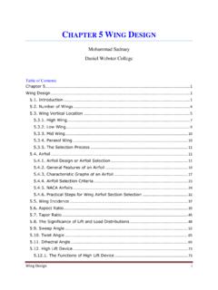
3 The A350 XWB-900 is the baseline layout of a family concept, which foresees also a stretched (-1000) and a shrinked version (-800), see Fig. 1. The -900 accommodates 315 passengers in a typical two class layout, providing a range of up to 7750 nautical miles. The maximum take-off weight is 268 tonnes. AIRBUS operations GmbH Fig. 1. Airbus A350 XWB aircraft family. Due to the work done already on the initial A350 and the challenging time scales, the concept phase of the A350 XWB was significantly shortened. The milestone, representing the end of the concept phase [1], took place in summer 2006 and the configuration development phase finished with the critical design review (CDR) in summer 2008.
4 Thus the overall aircraft design had to be frozen in two years time, which was a challenging task not only for the aerodynamics departments. THE AERODYNAMIC DESIGN OF THE A350 XWB-900 HIGH LIFT SYSTEM Henning Str ber* * AERODYNAMIC Design High Lift Devices, Airbus operations GmbH, Airbus-Allee 1, 28199 Bremen Keywords: A350 XWB-900 , High Lift, CFD, Wind Tunnel Test, Flight Test Henning Str ber 2 Enabling was on the one hand the consequent use of efficient design tools like 3D CAD systems and state of the art CFD codes, but also because of the traditionally high engagement of Airbus aerodynamics design departments in research projects. The focus was here on projects dealing with the multidisciplinary design of unconventional high-lift devices.
5 Those activities paved the way for selecting and assessing novel high-lift concepts in an efficient and multidisciplinary way as candidates for the A350 XWB. 2 The high-lift s ystem as an enabler to achieve aircraft design targets A light weight high-lift system with minimum complexity was requested, enabling the aircraft to achieve an outstanding climb performance during take-off, including hot and high conditions, leading to a low drag requirement a low approach speed (CAT D, Vappr 145kts) for safe approaches, supported by the large wing area leading to a moderate maximum lift (CLmax) requirement good handling qualities (A/C attitude in approach, pitch up characteristics, roll capabilities, etc.)
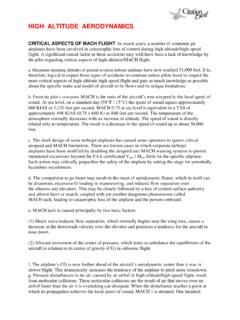
6 Favorable wake vortex characteristics low airframe noise to reduce impact on airport communities 3 High-lift devices on the A350 XWB-900 The layout of the wing movables is sketched in Fig. 2. The wing leading edge is equipped with a Droop Nose Device (DND) inboard and slats outboard. At the trailing edge two Adaptive Drooped Hinge Flaps (ADHF) are installed, covered by a droop panel and seven spoilers. Two ailerons are located outboard of the flaps. The AERODYNAMIC design process of the high-lift devices is presented in the following chapters. AIRBUS operations GmbH EGACD Fig. 2. A350 XWB-900 wing movable planform. Low drag leading edge devices The main purpose of leading edge devices is to protect the high-lift wing at high angle of attack ( ) against too early flow separation, meaning to shift the max and subsequently CLmax to higher values.
7 This is achieved by deploying the device and by that reducing the local angle of attack and is further increased by opening a slot between the leading and the trailing element. A detailed description of AERODYNAMIC effects in high-lift is given in [2] and [3]. A vented design solution is well suited to achieve CLmax targets for landing configurations, but is contradictive to keep the drag of a take-off configuration low. Also the noise emission of a vented leading edge device is significantly higher than for an un-slotted solution, see [4]. The selection and design of the A350 XWB-900 leading edge high-lift devices was driven by the requirement to achieve a maximum take-off L/D in the 2nd segment climb.
8 Hence a device type was needed, which provided a low drag level in take-off configuration, but sufficient protection against flow separation in landing to achieve the 3 THE AERODYNAMIC DESIGN OF THE A350 XWB-900 HIGH LIFT SYSTEM required CLmax values, respectively the approach speed targets. Inboard Wing the Droop Nose Device One challenge to solve was the integration of the 118 ( 3m) diameter Rolls-Royce Trent XWB nacelle with the leading edge high-lift devices. The close coupling of engine and pylon to the wing asked for an inboard high-lift device, which allows a close deployed positioning. The maximum lift capability of the wing is heavily influenced by the engine installation, leading to subsequent flow separation at high incidences.
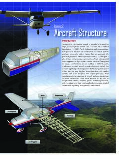
9 With the installation of a strake at the inboard nacelle, a high energy vortex is introduced to delay the separation towards higher incidences, see Fig. 5 and Fig. 17. It was found that a Droop Nose Device (DND) is a good choice for application on the inboard wing leading edge from AERODYNAMIC and integration point of view. The large wing chords in the inner wing region lead to low local lift coefficients. By deploying a DND, the local angle of attack is reduced far enough, to delay the stall. A typical pressure distribution over a wing section with DND can be found in Fig. 3. A moderate suction peak is followed by the characteristic second suction peak with approximately the same cp level.
10 Compared to a slat, the drag and also the noise level of a DND is much more favorable. AIRBUS operations GmbH - EGACD Fig. 3. 2D pressure distribution along a Droop Nose Device (DND) equipped wing. The DND in combination with the engine installation leads to favorable stalling mechanism, where the inboard wing stalls, while the flow over the outboard wing shall still be attached and the roll control surfaces are not yet affected by the stall. An undesired pitch up behavior of the aircraft , which occurs on highly swept wings when the flow in outboard regions separates, is avoided. The DND movable rotates on a hinge-line close to the wing lower surface, see Fig.