Transcription of The AMRAD Active LF Antenna
1 September 2001 31 TBy By By By By Frank Gentges, KFrank Gentges, KFrank Gentges, KFrank Gentges, KFrank Gentges, K BRABRABRABRABRAhe Amateur Radio Researchand Development Corporation( AMRAD ) is a nonprofit radio clubthat specializes in cutting-edge yetfun Amateur Radio technology. In ajump back to the future, several of usdecided to look into low-frequency radio(LF). Many European countries now havean Amateur Radio allocation at 136 kHz,and AMRAD , hoping for a future FCCamateur allocation there obtained anFCC Part 5 license to operate experimen-tally on those challenging low frequen-cies. Many hams wanted to listen to ourtransmissions, but lacked a suitable re-ceiving Antenna . The Antenna describedhere should do BackgroundThe evolution of our present antennahas a proud lineage.
2 AMRAD memberDick (WA3 USG) Goodman s MonsterLoop is an excellent Antenna and met ourinitial Another member, Bill Farmer,W3 CSW, built a loop Antenna in his atticthat also performs Low-frequencyveteran Ken Cornell, W2 IMB, describedseveral Active antennas, including hisvaractor-tuned Active And engi-neering whiz Andre Kesteloot, N4 ICK,presented an even better design. Hisvaractor-tuned Active Antenna has the tun-ing stage ahead of the FET s Antenna works very well, but likethe Cornell design, it must be tuned to thedesired frequency. Because of their sim-plicity and performance, Ralph Burhans Active - Antenna designs became popularThe AMRADA ctive LF AntennaYou can tune into LF activity with this easy-to-build and erect Active Antenna . As a bonus,you get MF and HF coverage, too not tomention world-class performance!
3 With LOWFers (low-frequency experi-menters) in the ,6 Even thoughthey re a few years old, Burhans articlesprovide important information about theworkings of Active antennas. These anten-nas were a starting point in our quest foran improved LF Active US Navy gave the club access tosome large LF transmitting antennas thatwere scheduled for demolition. We con-ducted a series of tests and concluded thatfor LF receiving, a well-designed activeantenna in a low-noise area can performas well as much larger ProjectThe Active Antenna described here canbe a powerful tool for the future LF-ac-tive ham seeking to work Europe and winthe Bobek LF Transatlantic Challenge(once an LF Amateur Radio band is allo-cated by the FCC, of course). For moreinformation about the Challenge, see1 Notes appear on page 1 Active Antenna response set out to build a transatlantic-grade LF Antenna that any ham couldbuild with simple hand tools.
4 We alsowanted our design to improve onBurhans IMD performance to enable ur-ban hams to receive the LF bands with-out dealing with spurious signals causedby IMD. We also wanted our Antenna towork to 30 MHz, if possible, to make theantenna generally more useful. We repleased to report that this Antenna exhib-its improved IMD performance and has auseful range of 10 kHz to 30 is an Active Antenna ?An Active Antenna is an electrically andphysically small Antenna combined withan Active electronic circuit, such as anamplifier. An Active Antenna , like the onedescribed here, uses a small whip onethat is a fraction of a wavelength long at32 September 2001the desired frequency connected to anactive impedance-conversion electrically short whip has a highoutput impedance. For example, a 1-meterwhip at 10 kHz has an input impedance ofalmost 2 M.
5 If such a whip were con-nected directly to a 50- load, signalsreaching the Antenna would be attenuatedalmost 114 dB by the time they reachedthe receiver. The Active impedance-conver-sion portion of this Antenna is a high-input-impedance FET follower feeding a50- load, eliminating much of the signalattenuation. In this design, the attenuationis only about 16 dB. Reducing the non-linearity and the resulting IMD productswas the major design the Burhans antennas haveIMD performance that exceeds that ofmany Active antennas, urban hams needeven better performance. After trying anumber of changes to Burhans designs,we found that performance could be im-proved by increasing the level at whichperformed well up to 30 MHz. Three ad-ditional antennas were built and used inAMRAD s annual LF expedition to NorthCarolina s Outer Banks an environmentthat has low LF noise and superb LFpropagation from Europe (as observed bymonitoring European LF broadcast sta-tions).
6 The singular problem is a CoastGuard Loran-C transmitter at CarolinaBeach, North Carolina. It operates on 100kHz, transmitting short, 600-kW the Outer Banks expedition, thenew Antenna performed well. It was sogood that the receiver, a modified Ten-TecRX-320, became the limiting A136-kHz filter placed between the antennaand the receiver solved the receiver IMDproblem and brought receiver sensitivitydown to the local noise SupplyThe power supply (see Figure 3) is de-signed to minimize coupling between thepower line, the Antenna and station power transformer chosen is theresult of carefully testing and sorting com-mercially available transformers. Simi-larly, the signals from the Antenna arecoupled to receiver ports RX1 and RX2through a wideband isolation transformer,T2. This prevents noise on the receiverground from coupling into the antennaground.
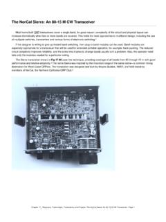
7 Isolation transformers such as thishave been invaluable in reducing noisecoupling in LF receiving power supply has a provision (J4)for using an external 24-V dc source (ie,a battery) for portable operation. 1- or2-Ah gel-cells provide power for severalhours given the 53-mA Antenna is designed to work intoa 50- load. Ideally, a 50- receiver isattached to RX1 and a high-impedancedevice, such as an oscilloscope orcounter, is connected to RX2. Althoughthe output impedance of RX1 and RX2 isabout 14 , a load less than 50 de-grades the IMD performance. Runningmultiple receivers on a single Antenna hasFigure 2 The heat sink is made from a 41/2-inch piece of 3/4-inch copper pipe cut andshaped as shown. Cut pairs of 1/4-inch deep slots at the A points indicated. Theseform tabs that center the pipe in the PVC tube (see text and Figure 5).
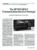
8 Figure 4 The amplifier, heat sink and PVC tube 3 An interiorview of the power supplyenclosure and circuit began and by using a more lineartransistor. The problem with increasing theclipping level is that the transistor operat-ing voltage and the bias current almostcertainly increase, resulting in increasedpower dissipation by the , we received some keydesign details from Dr Dallas Lankford,who was working on an HF identified the Crystalonics CP-640/CP-650 series of junction FETs as out-standingly linear for Active Antenna ap-plications. He was kind enough to sharehis design ideas and provide help with ourIMD measurements. AMRAD kudos goto Dallas for his increased transistor heat dissipa-tion is handled by a homemade heat sinkconstructed from 3/4-inch copper available PVC pipe fittings makea protective enclosure for the PC-board prototype was built usinga resist pen printed circuit board and, af-ter a few trials and changes, the antennaSeptember 2001 33turned out to be very handy at Antenna achieves very goodintermodulation and overload perfor-mance at some sacrifice in output AMRAD amplifier is based onBurhans noiseless feedback design.
9 Thefrequency response curve for the an-tenna with a 1-meter whip is shown inFigure 1. The input capacitance of theactive amplifier is about 29 member Steve Ratzlaff,AA7U, helped measure the second- andthird-order intercept points. Overload andintermodulation performance are mea-sured much as they would be for an RFamplifier or For second- andthird-order intercept point measurements,a hybrid combiner is We used alower-frequency transformer for the hy-brid that consisted of 25 bifilar turns of#30 wire on an Amidon FT-87-J ferritetoroid signals were fed through a 12-pFcapacitor to simulate the source imped-ance of a 1-meter whip. Referenced to theantenna output, the following values weremeasured: 1-dB compression point,+25 dBm; second-order intercept point,+53 dBm; third-order intercept point,+37 performance of the AMRAD an-tenna considerably exceeds that of everyreadily available Active Antenna we can expect similar performance, savefor the last 5 dB or so of second-orderIMD performance, which may have to besqueezed out using a test setup to fine-tune the bias second-order intercept point re-lates to the Antenna s distortion product(f1 f2).
10 Second-order intercept valuesoften take a back seat to the more com-monly measured third-order values. Theybecome important in LF listening, how-ever, because second-order distortionproducts can create spurious signals inthe LF band in the presence of two localAM broadcast stations; the higher thenumber, the lower the distortion number in no way implies that theantenna can withstand a signal-input levelof +53 dBm, much less perform usefullyunder such can build the Antenna usingreadily available hand tools. The PCboards are available from FAR only required adjustments are settingthe power supply voltage to 24 V and set-ting the amplifier transistor bias for asource current of 53 is special and available only fromCrystalonics, which specializes in high-performance RF devices. Although thecompany usually doesn t sell single de-vices, it has kindly agreed to sell them toreaders of this CasePrepare the pieces of Schedule 40 PVC pipe as follows:Cut an 8-inch-long piece of 1-inchSchedule 40 PVC pipe (the amplifiercase).