Transcription of The Basics of Signal Attenuation - CAS Dataloggers
1 WHITE PAPER Maximize Signal Range and Wireless Monitoring Capability Attenuation is a reduction of Signal strength during transmission, such as when sending data collected through automated monitoring. Attenuation is represented in decibels (dB), which is ten times the logarithm of the Signal power at a particular input divided by the Signal power at an output of a specified medium. For example, an office wall (the specific medium) that changes the propagation of an RF Signal from a power level of 10 milliwatts (the input) to 5 milliwatts (the output) represents 3 dB of Attenuation .
2 Consequently, positive Attenuation causes signals to become weaker when travelling through the medium. When Signal power decreases to relatively low values, the receiving radio will likely encounter bit errors when decoding the Signal . This problem worsens when significant RF interference is present. The occurrence of bit errors causes the receiving station to refrain from sending an acknowledgement to the source station. After a short period of time, the sending station will retransmit the frame. In the worst case, Signal power loss due to Attenuation becomes so low that the system loses connectivity to the network gateway.
3 The Signal strength indicator is the Link Quality Indication (LQI) measurement based on the bit error rate [BER] of the current packet being received from the previous hop of the inbound route, so that it provides information specific to the link-layer connection to the neighboring device relaying the current packet to the local device. Causes of Attenuation in both Signal frequency and range between the end points of the medium, affect the amount of Signal reduction. As the range increases, Attenuation also increases. Attenuation in outdoor applications is based on straightforward and basic free space, but in contrast, indoor applications can be very complex to calculate.
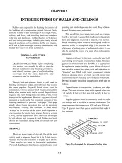
4 In both cases, loss formulas can be used (see Equation 1 and Equation 2). The main reason for the indoor difficulty is that indoor signals bounce off obstacles and penetrate a variety of materials that offer varying effects on Attenuation (see Table 1-2 Obstacle Attenuation ). THE Basics OF Signal Attenuation The Basics of Signal Attenuation 1 WHITE PAPER Free Space Loss Formulas Items with losses to be added dB: Human body 3 Cubicles 3 to 5 Window, Brick Wall 2 Brick Wall next to a Metal Door 3 Glass Window (non tinted)
5 2 Clear Glass Window 2 Office window 3 plasterboard wall 3 Marble 5 Glass wall with metal frame 6 Metal Frame Glass Wall Into Building 6 The Basics of Signal Attenuation 2 WHITE PAPER Metal Frame Clear Glass Wall 6 Metal Screened Clear Glass Window 6 Wired-Glass Window 8 Cinder block wall 4 Dry Wall 4 Cinder Block Wall 4 Sheetrock/Wood Frame Wall 5 Sheetrock/Metal Framed Wall 6 Office Wall 6 Brick Wall 2 to 8 Concrete Wall 10 to 15 Wooden Door 3 Metal door 6 Metal Door in Office Wall 6 Metal door in brick wall 12 to 13 Table 1-2 Obstacle Attenuation As a result, it s often necessary to perform an RF site survey to fully understand the behavior of radio waves within a facility before installing wireless network gateways.
6 The ultimate goal of the survey is to supply enough information to determine the number and placement of pods and wireless network gateways to provide adequate coverage throughout the facility. An RF site survey also detects the presence of interference coming from other sources that could degrade the performance of the system. The need and complexity of an RF site survey will vary depending on the facility, a small three-room office may not require a site survey the site will probably get by with a single wireless network gateway located anywhere within the office and still maintain adequate coverage.
7 A larger facility, such as an office complex, apartment building, hospital, or warehouse generally requires an extensive RF site survey. Without a survey, the system may end up with inadequate coverage and suffer from low performance in some areas. When conducting an RF site survey, consider these general steps: The Basics of Signal Attenuation 3 WHITE PAPER 1. Obtain a facility diagram. Locate a set of building blueprints, if possible. If none are available, prepare a floor plan drawing that depicts the location of walls, walkways, etc.
8 2. Visually inspect the facility. Be sure to walk through the facility before performing any tests to verify the accuracy of the facility diagram. This is a good time to note any potential barriers that may affect the propagation of RF signals, a visual inspection will discover obstacles such as metal racks and partitions items that blueprints don t show. 3. Identify user areas. On the facility diagram, mark the areas where fixed and mobile pods are to be placed. In addition to illustrating where mobile pods may be moved around, also indicate where they will not be placed.
9 The system may require fewer wireless network gateway points if roaming areas can be limited. 4. Determine preliminary access point locations. By considering the location of pods and range estimations between pods and gateways, estimate the locations of gateways to provide adequate coverage throughout the area (preliminary locations). Consider mounting locations, which could be vertical posts or metal supports above ceiling tiles. Be sure to recognize suitable locations for installing the access point, antenna, data cable and power line. Also think about different antenna types when deciding where to position access points.
10 An access point mounted near an outside wall, for example, could be a good location if a patch antenna with relatively high gain is oriented within the facility. 5. Verify access point locations. This is when the real testing begins: it s a two-person job. Install a wireless network gateway at each preliminary location and monitor the Signal strength indicator readings by walking with a pod for varying distances away from the access point. Take note of data rates and Signal readings at different points as the pod is moved to the outer bounds of the gateway s coverage. In a multi-floor facility, perform tests on the floor above and below the access point.