Transcription of The Broadband Double-Bazooka Antenna — How Broad Is It?
1 The Broadband Double-Bazooka Antenna How Broad Is It? 18-1(Adapted from Technical Correspon-dence, QST, September 1976)Sec IntroductionThe increasing interest in usingthe coaxial dipole (sometimescalled the Double-Bazooka an-tenna) for its questionable in-creased bandwidth is disturbing, espe-cially in view of the results of an analysisand some experiments I performed andpublished several years ago. The Antenna ,with its inner section of coax and its endsections of open-wire transmission line(ladder line), was popularized for amateuruse by Charles Whysall, W8TV, with anarticle in July 1968 QST (Ref 29). It ap-pears in several editions of The ARRLH andbook, although it has never ap-peared in The ARRL Antenna Book. Theresults of my analysis and experimentsindicate that the coaxial stubs in the co-axial-dipole configuration in general useby amateurs cannot provide the degree ofbandwidth that users of the coaxial dipoleappear to be measuring.
2 Thus, it appearsthat features other than the shunt-com-pensating reactance provided by the co-axial stubs within the dipole must be re-sponsible for achieving the bandwidthcredited to the coaxial s why the shunt-reactance com-pensating feature cannot make any sig-nificant contribution to bandwidth whenthe feed-line impedance is the usual ZC =50 ohms. Depending on the height aboveground, the input impedance of the aver-age 40-meter or 80-meter amateur dipolegenerally runs from 50 to 80 ohms of re-sistance at resonance. Thus, at resonance,the mismatch on a 50-ohm line is gener-ally quite low, from less than to at worst. On either side of resonance,the mismatch increases rapidly becauseof the reactance appearing in the dipoleimpedance. With the addition of the co-axial reactance-compensating shuntstubs, the dipole reactance should be ei-ther canceled at best, or at worst, reducedsomewhat by the opposite shunt reactanceprovided by the ReactanceCancellationChapter 18 The Broadband double -BazookaAntenna How Broad Is It?
3 Although you ll see later why it can tbe, let s first assume hypothetically thatcomplete cancellation of the reactance canbe achieved by the shunt reactance of thecoaxial stubs. This means the cancella-tion is obtained by a parallel-connectedreactance, which raises the series resis-tance of the dipole impedance to itsequivalent parallel-circuit value, which ismuch higher. And here is the crucialpoint. When you use a feed line havingan impedance which already matches thedipole terminal resistance rather well atresonance, the higher mismatch off reso-nance caused by the dipole reactance willnot be significantly different, whether itis caused by the reactance of the uncom-pensated dipole or by the increased resis-18-2 Chapter 18tance received in exchange for the can-celed illustrate with an example, con-sider an 80-meter dipole at a height whichyields a resonant terminal impedance of55 + j0 ohms at MHz.
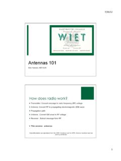
4 The mismatchis referred to 50 ohms. At MHz,200 kHz below resonance, the series im-pedance of the dipole is approximately 50 j90 ohms, which yields a :1 mis-match. Now a 90-ohm inductive reactanceplaced in series with the dipole terminalswould cancel the 90-ohm capacitive dipolereactance, and would leave the terminalresistance at 50 ohms. And we would in-deed have a perfect 18-1 Showing the impedance transformation for (A) center coaxial section,and (B) 50-ohm center section. At both A and B, the SWR without coaxial stubs is :1;with stubs at A it becomes :1, and in the practical case at B, Broadband Double-Bazooka Antenna How Broad Is It? 18-3 Unfortunately, the reactance pro-vided by the stubs in the coaxial dipole isin parallel with the dipole terminal im-pedance, not in series. And what a differ-ence this makes! The values of the equiva-lent parallel-circuit components of thedipole impedance at MHz (50 j90ohms) are RP = 212, and XP = ohms,as shown in Fig 18-1A.
5 When the of capacitive dipole reactance is com-pletely canceled by an equal inductivereactance in parallel with the dipole im-pedance, the resulting impedance is 212+ j0 ohms. Bad news! The terminal resis-tance of the dipole made resonant at by the shunt inductive reactance isnow 212 ohms, raised from 50 ohms bythe parallel connection! Canceling the di-pole reactance with parallel circuitry hasraised the resistive component by a fac-tor of from 50 ohms up to 212 ohms,and coincidentally, the mismatch is now212/50 = :1. This is the lowest mis-match obtainable with any type of paral-lel compensation, because even thoughthe dipole reactance has been completelycanceled, we re still stuck with the 212-ohm dipole terminal , a reduction in mismatchfrom :1 to :1 is hardly worthwhile,even if it could be accomplished. But itcan t. Why? Because a canceling reactanceof ohms would require a coax hav-ing a characteristic impedance ZC of ohms for the stubs impractical tobuild.
6 Here s more bad news: Stubs madefrom 50-ohm coax yield a reactance tentimes too high useless. What about 75-ohm coax? times worse. Incredible,you say? Example continues: A short-cir-cuited stub, /4 resonant at MHzmade from 50-ohm coax, yields an induc-tive reactance of ohms at MHz,again 200 kHz below resonance. Thesevalues are calculated from the followingequations below at MHz. (Eq 18-1)Shunting reactance per stubX = ZC tan = ohms(Eq 18-2)when stub ZC = 50 ohms, and = Stub impedance required, each stub(Eq 18-3)when X = ohms, and = ZC = X cot = ohms2 The stubs in each dipole half ( each) are connected in series witheach other through their center conduc-tors, so the total inductive reactance ofthe series combination is twice the valueof the single stub, or ohms. This isthe value appearing in parallel with thedipole impedance when using 50-ohmstubs.
7 (Stubs of 75 ohms would ohms.) The combined parallel com-ponents of the dipole impedance andshunt-stub reactance (RP = 212 ohms andXP = ohms in parallel with stubs of+ ohms) yield total parallel-circuitcomponent values of RP = 212 ohms andXP = ohms. The series-equivalentdipole input-terminal impedance is ohms, also shown in Fig 18-1at B. The result? A whopping big reduc-tion in mismatch from without stubs,all the way down to :1 with stubs! Go-ing still further, using the stubs that would cancel all thedipole reactance, the resulting non-reac-tive dipole terminal impedance of 212 +j0 ohms would still yield a :1 SWR onthe 50-ohm feed line. Conclusion? Isn t itobvious that the stubs are ineffective? Andshouldn t it be disturbing?So you ask what other features canbe responsible for the lower mismatchvalues that appear to be measured byStub length = 90 = MHz18- 4 Chapter 18many coaxial-dipole users.
8 I ll give you anumber of , the mismatch values shownhere are those which appear at the junc-tion of the feed line and the Antenna , whilevalues measured at the input of the feedline will be somewhat lower because ofline , increased radiator thickness,especially when the stubs are constructedfrom RG-8, reduces the dipole character-istic impedance, resulting in less reac-tance than with the thinner wire dipolefor the same frequency excursion awayfrom resonance. (But who wants to hang125 feet of RG-8?)Third, the extensions for building outfrom the shortened, short-circuited endsof the coax stubs to obtain an external halfwave are usually of multiwire construc-tion such as ladder line, which furtherincreases the effective radiator is especially helpful at the outer endsof the dipole, where the voltage and theelectric field are high. This reduces theoff-resonance reactance still , the external dielectric mate-rial covering the stub coax increases bothdipole capacitance (increasing the electri-cal length) and effective diameter of theradiator.
9 However, indications under in-vestigation suggest this increase in effec-tive diameter is also accompanied by in-creased ohmic loss in the external dielec-tric, which decreases the Q, and thus in-creases the bandwidth at the expense fifth, in the range above 3:1,many SWR indicators show readings con-siderably lower than the true value. If youare interested in pursuing the subject fur-ther, I invite you to read my paper en-titled, A Revealing Analysis of the Co-axial Dipole Antenna , appearing on page46 of Ham Radio for August, 1976 (Ref62).Sec Resistive LossesSince I wrote the Technical Corre-spondence item on which the above infor-mation is based, the true reason for theincreased dipole bandwidth obtained withthe Double-Bazooka has been the reason is not a happy one. FrankWitt, AI1H (ex-W1 DTY), with the aid of acomputer, has discovered that the in-creased bandwidth of the double -Bazookaobtained by many amateurs actuallyarises from the previously undeterminedresistive loss due to the shunt conductionof the internal dielectric material in thecoaxial cable used to form the stubs, andnot by reactance cancellation from paral-lel-connected coaxial stubs (Ref 122).
10 Inother words, the reduction in SWR ob-tained by those who use the double -Ba-zooka is from lossy resistive loading, andnot from reactance cancellation. Unfortu-nately, the resistive loading results in areduction in radiated power, power lostin heating the stubs. Thus the users ofthis Antenna are trading radiated powerfor a lower SWR on the feed turn of events is ironic for tworeasons. First, as I showed earlier, thereactance available in the coaxial stubsin the Double-Bazooka is insufficient toobtain any practical amount of reductionin the SWR-producing Antenna -terminalreactance, much less total second, even if the stubs could pro-vide sufficient reactance to obtain com-plete cancellation, the improvement inbandwidth would still have been inconse-quential as a result of the cancellation,as I proved in this chapter, and in my co-axial dipole analysis (Ref 62), I pointedout the reason no bandwidth improvementis possible from parallel-circuit reactancecancellation when the feed line impedanceis 50 ohms.