Transcription of The Delta Parallel Robot: Kinematics ... - Ohio University
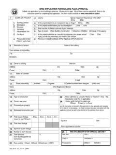
1 The Delta Parallel Robot: Kinematics Solutions Robert L. Williams II, , mechanical Engineering, ohio University , October 2016 Clavel s Delta Robot1 is arguably the most successful commercial Parallel robot to date. The left image below shows the original design from Clavel s patent2, and the right photograph below shows one commercial instantiation of the Delta Robot. Delta Robot Design1 ABB FlexPicker Delta Robot The Delta Robot has 4-degrees-of-freedom (dof), 3-dof for XYZ translation, plus a fourth inner leg to control a single rotational freedom at the end-effector platform (about the axis perpendicular to the platform).
2 The remainder of this document will focus only on the 3-dof XYZ translation-only Delta Robot since that is being widely applied by 3D printers and Arduino hobbyists. Presented is a description of the 3-dof Delta Robot, followed by Kinematics analysis including analytical solutions for the inverse position Kinematics problem and the forward position Kinematics problem, and then examples for both, snapshots and trajectories. The velocity equations are also derived This is presented for both revolute-input and prismatic-input Delta Robots. For referencing this document, please use: Williams II, The Delta Parallel Robot: Kinematics Solutions , Internet Publication, , January 2016.
3 1 R. Clavel, 1991, Conception d'un robot parall le rapide 4 degr s de libert , Thesis, EPFL, Lausanne, Switzerland. 2 R. Clavel, 1990, Device for the Movement and Positioning of an Element in Space , Patent No. 4,976,582. 2 Table of Contents REVOLUTE-INPUT Delta ROBOT .. 3 REVOLUTE-INPUT Delta ROBOT DESCRIPTION .. 3 REVOLUTE-INPUT Delta ROBOT MOBILITY .. 7 PRACTICAL REVOLUTE-INPUT Delta ROBOTS .. 9 REVOLUTE-INPUT Delta ROBOT Kinematics ANALYSIS .. 10 Inverse Position Kinematics (IPK) Solution .. 11 Forward Position Kinematics (FPK) Solution .. 12 Revolute-Input Delta Robot Velocity Kinematics Equations.
4 15 REVOLUTE-INPUT Delta ROBOT POSITION Kinematics EXAMPLES .. 16 Inverse Position Kinematics Examples .. 16 Forward Position Kinematics Examples .. 19 PRISMATIC-INPUT Delta ROBOT .. 22 PRISMATIC-INPUT Delta ROBOT DESCRIPTION .. 22 PRISMATIC-INPUT Delta ROBOT PARAMETERS .. 25 PRACTICAL PRISMATIC-INPUT Delta ROBOTS .. 26 PRISMATIC-INPUT Delta ROBOT Kinematics ANALYSIS .. 27 Inverse Position Kinematics (IPK) Solution .. 28 Forward Position Kinematics (FPK) Solution .. 30 Prismatic-Input Delta Robot Velocity Kinematics Equations .. 35 PRISMATIC-INPUT Delta ROBOT POSITION Kinematics EXAMPLES .. 36 Inverse Position Kinematics Examples.
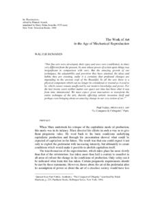
5 36 Forward Position Kinematics Examples .. 39 ACKNOWLEDGEMENTS .. 40 APPENDICES .. 41 APPENDIX A. THREE-SPHERES INTERSECTION ALGORITHM .. 41 Example .. 43 Imaginary Solutions .. 43 Singularities .. 43 Multiple Solutions .. 44 APPENDIX B. SIMPLIFIED THREE-SPHERES INTERSECTION ALGORITHM .. 45 3 Revolute-Input Delta Robot Revolute-Input Delta Robot Description As shown below, the 3-dof Delta Robot is composed of three identical RUU legs in Parallel between the top fixed base and the bottom moving end-effector platform. The top revolute joints are actuated (indicated by the underbar) via base-fixed rotational actuators.
6 Their control variables are ,1,2,3ii about the axes shown. In this model i are measured with the right hand, with zero angle defined as when the actuated link is in the horizontal plane. The parallelogram 4-bar mechanisms of the three lower links ensure the translation-only motion. The universal (U) joints are implemented using three non-collocated revolute (R) joints (two Parallel and one perpendicular, six places) as shown below. Delta Parallel Robot Diagram adapted from: 4 The three-dof Delta Robot is capable of XYZ translational control of its moving platform within its workspace. Viewing the three identical RUU chains as legs, points ,1,2,3iBi are the hips, points ,1,2,3iAi are the knees, and points ,1,2,3iPi are the ankles.
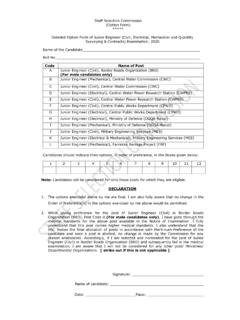
7 The side length of the base equilateral triangle is sB and the side length of the moving platform equilateral triangle is sP. The moving platform equilateral triangle is inverted with respect to the base equilateral triangle as shown, in a constant orientation. Delta Robot Kinematic Diagram The fixed base Cartesian reference frame is {B}, whose origin is located in the center of the base equilateral triangle. The moving platform Cartesian reference frame is {P}, whose origin is located in the center of the platform equilateral triangle. The orientation of {P} is always identical to the orientation of {B} so rotation matrix 3BP RI is constant.
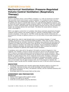
8 The joint variables are 123T , and the Cartesian variables are TBPxyz P. The design shown has high symmetry, with three upper leg lengths L and three lower lengths l (the parallelogram four-bar mechanisms major lengths). The Delta Robot fixed base and platform geometric details are shown on the next page. 5 Delta Robot Fixed Base Details Delta Robot Moving Platform Details 6 The fixed-base revolute joint points iB are constant in the base frame {B} and the platform-fixed U-joint connection points iP are constant in the base frame {P}: 100 BBw B 232120 BBBww B 332120 BBBww B 100 PPu P 220 PPPsw P 320 PPPsw P The vertices of the fixed-based equilateral triangle are: 120 BBBsw b 200 BBu b 320 BBBsw b where.
9 36 BBws 33 BBus 36 PPws 33 PPus name meaning value (mm) sB base equilateral triangle side 567 sP platform equilateral triangle side 76 L upper legs length 524 l lower legs parallelogram length 1244 h lower legs parallelogram width 131 wB planar distance from {0} to near base side 164 uB planar distance from {0} to a base vertex 327 wP planar distance from {P} to near platform side 22 uP planar distance from {P} to a platform vertex 44 The model values above are for a specific commercial Delta robot, the ABB FlexPicker IRB 360-1/1600, scaled from a figure ( ).
10 Though Delta Robot symmetry is assumed, the following methods may be adapted to the general case. 7 Revolute-Input Delta Robot Mobility This section proves that the mobility (the number of degrees-of-freedom) for the Delta robot is indeed 3-dof. Using the spatial Kutzbach mobility equation for the previous Delta Robot figure: 1236(1) 543 MNJJJ where: M is the mobility, or number of degrees-of-freedom N is the total number of links, including ground J1 is the number of one-dof joints J2 is the number of two-dof joints J3 is the number of three-dof joints J1 one-dof joints: revolute and prismatic joints J2 two-dof joints: universal joint J3 three-dof joints: spherical joint For the as-designed Delta Robot, we have.