Transcription of The End Fed Half Wave Antenna - gnarc.org
1 November 14, 2018 Steve Dick, K1RF 1 About Half-wave Antennas A half-wave Antenna is a resonant radiating element with an electrical length of one half-wave. Total length in feet. ~468 / freq in Mhz. Its feed-point affects its impedance. High current, low voltage at center; low current high voltage at ends. The most common half-wave Antenna is the center-fed dipole, whose impedance is approximately 72 ohms. A dipole is basically a mono-band Antenna . It is sometimes used on its 3rd harmonic with coax, or used multiband as a doublet with balun, ladder line and wideband tuner.) If fed off center, say at 30%-70% point, impedance is approximately 200 ohms and can be used on multiple bands with an Antenna tuner.
2 Works with a 4:1 UNUN. See this link for more info. 4:1 impedance ratio is 2:1 turns ratio. If fed at the end ( EFHW), Antenna impedance is in the 2000-4000 ohms range. It requires a high impedance matching device: Either a tapped resonant circuit, a Zepp type coupling circuit, or a high impedance ratio UNUN (49:1 or 64:1) It can be used on multiple bands. With a 49:1 or 64:1 UNUN, no tuning is required and no Antenna tuner is required (or perhaps a touch up tuner with up to 3:1 VSWR capability that many modern rigs have built-in.) 2 What are the advantages of an EFHW fed with an UNUN compared to other wire antennas? Ease of installation. Only a single high point required Many configurations possible to suit your installation: Horizontal, Inverted V, Inverted L, Sloper, etc No hanging feedline.
3 Feed point is near the ground. Minimal ground system or counterpoise needed the coax feed itself can act as a counterpoise Resonant on 80/40/30/20/17/15/12/10m with low VSWR. No tuner needed or just a 3:1 Touch-up tuner One simple length adjustment no interactions between bands. Grounded at No static buildup. Shortened versions possible for limited area 3 Multiband operation of a Half-Wave Antenna If the half-wave Antenna can be impedance matched on all of its harmonics, you now have a multiband Antenna . On the fundamental frequency, Antenna pattern is identical no matter where you feed it. 4 But a key characteristic that does change is the radiation pattern on each harmonic. This IS affected by where the half-wave is fed.
4 X 1 = MHz 80M x 2 = MHz 40M x 3 = MHz 30M x 4 = MHz 20M x 5 = MHz 17M x 6 = MHz 15M x 7 = MHz 12M x 8 = Mhz 10M Conventional 1:4 and 1:9 UNUNs These UNUNs belongs to a class of devices known as transmission line transformers , which are formed by winding bifilar turns, multi-filar turns, coaxial cable, or stripline cable (two strips of the flat conductor with a dielectric material between the strips) on a core having high permeability. 1:4 UNUNs (Zout=200 ohms) are typically used for off-center-fed (OCF) dipoles, Zepps, and 43 foot multiband verticals and random length (non-resonant) wires 1:9 UNUNs (Zout=450 ohms) are typically used with random length non-resonant wire antennas At low frequencies, like all transformers, they require adequate primary inductance at lowest freq.
5 Standard Transformer Pri Strt Pri End Sec Strt Sec End Pri Strt Sec Strt Sec End Pri End Transmission line (twisted or parallel pair) Bifilar Wound Transmission Line Transformer Balun Designs Pri Sec Transmission line transformers exhibit very wide bandwidth (1-54 MHz), high power capability (2-5KW), and high efficiency Some Applications of the 4:1 UNUN Variants of the modern W3 EDP Zepp Off-Center-fed Antenna 6 These usually require wide range Antenna tuner Courtesy Tom, K1TA Courtesy Balun Designs 160 through 6 meters! 4:1 balun is wideband and allows this to work. Requires wideband tuner: High SWR on even harmonics and more feedline radiation Application of 9:1 UNUN Emergency Amateur Radio Club of Hawaii (EARCHI) marketed a matchbox-kit for a 6-40 mtr multi-band end-fed Antenna .
6 Uses non-resonant Antenna (Recommended Antenna wire length: 24-30 ft (60 ft max) and powdered iron toroid, efficient transmission line transformer 7 Short Non-resonant Antenna requires wide range Antenna tuner T130-2 High Impedance UNUN for EHFW Antenna The UNUN has a high impedance ratio (49:1 to 64:1) not feasible to use transmission line transformers whose practical limit is about 16:1. It is a conventional transformer. Uses a ferrite toroidal core or cores (usually Type 43 or type 52 material). Most 1:4 and 1:9 transmission line UNUNs use powdered metal cores (such as -6) having much lower permeability, not suited for an EFHW UNUN. Bandwidths support about a 10:1 frequency bandwidth (3-30 MHz) Two important UNUN parameters are core primary inductance and efficiency.)
7 8 Less bandwidth (80-10M) and more lossy than the 4:1 or 9:1 UNUNs --- But it still works fine and does the job. High Impedance UNUN for EHFW Antenna cont d Primary inductance If primary inductance is too small at the low frequency end, Mismatch loss is significant and high VSWR results. If primary inductance is too high, the high frequency performance suffers and VSWR climbs at the high end. My rule of thumb: Inductive reactance (XL) should be in the 88 ohm- 200 ohm range at the lowest frequency of use (XL = * F * L where (XL is inductive reactance in ohms, F is frequency in MHz, and L is inductance in microhenrys. ). This corresponds to 4-9 microhenrys at or microhenrys at 7 MHz . Toroid primary inductance increases with size of toroid.)
8 Two FT140 sized toroids have about the same inductance as a single FT-240 sized toroid for the same number of turns. Toroid primary inductance is proportional to the number of toroids. 9 Efficiency Good designs should support efficiencies in the range of 80-90%+ For signal strength, It makes little difference. For dissipated power in the toroid(s), it makes a big difference. At 50 watts continuous and 75% efficient toroid(s), power dissipation in the toroid is watts. At 50 watts continuous and 85% efficient toroid(s), power dissipation is watts: 60% of the 75% efficient toroid! CW duty cycle is ~ 44% of continuous power SSB duty cycle is ! 25% of continuous power 10 High Impedance UNUN for EHFW Antenna cont d EFHW UNUN Construction 11 I recommend at least 2 toroids for better efficiency, higher primary inductance, and splitting power between toroids I recommend 2 type 43 material for less than ~250 watts for lower cost, Fair Rite P/N 5943003801 3 type 52 material for ~500-1000W higher efficiency and higher temperature capable.
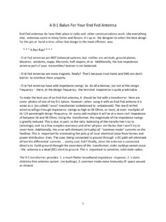
9 Fair Rite P/N 5952003801 Number of turns = number inside the toroid stack. Crossover counts as one turn Crossover EHFW Antenna Construction 12 UNUN Ground rod Coax Choke balun (Optional) Rig Coax Counterpoise (optional) Inverted L shown (Recommended). Never run Antenna wire next to a tower. Mount UNUN near top of tower instead. The coax going to the UNUN can serve as a counterpoise. A separate counterpoise wire is optional. A choke balun is optional but must be installed near the rig, never near the UNUN Mount UNUN 1-10 ft from ground. Lower is better. Compensation coil (Optional) EFHW Counterpoise Current flowing into the Antenna 's end must be equaled, at that end point, by the same amount of current flowing into a ground or counterpoise of some type.
10 In spite of what some manufacturers will tell you, an end-fed 1/2 wave ALWAYS has a counterpoise. If you don't specifically provide one then the coax shield will act as the counterpoise. For a suspended counterpoise wire, the "ideal" length would be 1/4 wavelength. That would provide the lowest impedance on the common side of the feed point and send the greatest amount of power into the Antenna and minimize any RF on the outside of the coax shield. Because the feed impedance on an end-fed 1/2 wave is high, you can get away with a lot shorter counterpoise. The higher your counterpoise impedance, the more current will flow in the outside of the coax shield, so its a trade off. Many get away with just using the coax shield as the counterpoise (which some manufacturers advertise as "no counterpoise").