Transcription of The engineer or designer must choose among P - …
1 - 4 . - . ,. * '. I c 4 ' W. M. Huitt W. M. Huitt Co. P ipe flanges are used to me- chanically connect pipe sections to other pipe sections, inline components, and equipment. Flanges also allow pipe to be assem- bled and disassembled without cut- ting or welding, which eliminates the need for those two operations when dismantling is required. In providing a breakable joint, however, flanges unfortunately provide a potential leak path for the process fluid contained in the pipe. Because of this, the usage of flanges needs to be minimized where possible, as with all other joints. The most prevalent flange stan- dards to be used in the process in- dustries are based on those of the American Soc.
2 Of Mechanical Engi- neers (ASME). These include: - Cast Iron Pipe Flanges and Flanged Fittings - Pipe Flanges and Flanged Fit- tings (NPS 1/2 through NPS 24, -.,:where NPS is nominal pipe size; see .. Part 1 of this series, CE, February, ' 'pp. 42-47) - Cast Copper Alloy Pipe Flanges and Flanged Fittings - Orifice Flanges - Ductile Iron Pipe Flanges and Flanged Fittings Large Diameter Steel Flanges (NPS* 26 through NPS 60) -Large Diameter steel flanges (NPS 26 through NPS 60) *NPS, indicated above, is an acronym for Nomi- nal Pipe Size. The engineer or designer must choose among several flange options. Additional decisions involve facing and surface finishes, and the appropriate.
3 , gaskets, bolts and nuts Flanges are available with various contact facings (the flange-to-flange contact surface) and methods of con- necting to the pipe itself. The flanges under , a standard widely rel- evant to the process industries, are available in a variety of styles and pressure classifications. The differ- ent styles, or types, are denoted by the way each connects to the pipe itself andlor by the type of face. The types of pipe-to-flange connections include the following: Threaded Socket welding (or socket weld) slip -on welding (or slip on) Lapped (or lap joint) Welding neck (or weld neck ) Blind Flange types Threaded.
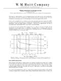
4 The threaded flange (Fig- ure I), through Class 400, is connected to threaded pipe in which the pipe thread conforms to ASME For threaded flanges in Class 600 and higher, the length through the hub of the flange exceeds the limitations of ASME ASME requires that when using threaded flanges in Class 600 or higher, Schedule 80 or heavier pipe wall thickness be used, and that the end of the pipe be reason- ably close to the mating surface of the flange. Note that the term "reasonably close* is taken, in context, from Annex A of ASME ; it is not quantified. In order to achieve this "reasonably close" requirement, the flange thread has to be longer and the diameters of the smaller threads must be smaller than that indicated in ASME When installing threaded flanges Class 600 and higher, ASME recommends using power equipment to obtain the proper engagement.
5 Sim- ply using arm strength with a hand wrench is not recommended. The primary benefit of threaded flanges is in eliminating the need for welding. In this regard, these flanges are sometimes used in high-pressure service in which the operating temper- ature is ambient. They are not suit- able where high temperatures, cyclic conditions or bending stresses can be potential problems. Socketweld: The socketweld flange is made so that the pipe is inserted into the socket of the flange until it hits the shoulder of the socket. The pipe is then backed away from the shoulder approximately 1/16 in. before being welded to the flange hub.
6 F 56 CHEMICAL ENGINEERING MARCH 2007 I I I FIGURE 1. Threaded flanges need not be welded FIGURE 3. slip -on flanges offer an initial lower cost FIGURE 2 Socketweld flanges have been commonly used FIGURE 4. A lapjoint flange can yield savings In material for small pipe sizes costs If the pipe were resting against the shoulder (this is the flat shelf area depicted in Figure 2 as the differ- ence between diameters B and B2) of the socket joint during welding, heat from the weld would expand the pipe longitudinally into the shoulder of the socket, forcing the pipe-to-flange weld area to move. This could cause the weld to crack.
7 The socketweld flange was initially developed for use on small size, high- pressure piping in which both a back- side hub weld and an internal shoul- der weld was made. This provided a static strength equal to the slip -on flange (discussed below), with a fa- tigue strength times that of the slip -on flange. Because having two welds was labor intensive, it became the prac- tice to weld only at the hub of the flange. This practice relegated the socketweld flange to be more fre- quently used for small pipe sizes (NPS 2 in. and below) in non-high- pressure, utility type service piping. The socketweld flange is not ap- proved above Class 1500.
8 slip on: Unlike the socketweld flange, the slip -on flange (Figure 3) allows the pipe to be inserted completely through its hub opening. Two welds are made to secure the flange to the pipe. One fillet weld is made at the hub of the flange, and the second weld is made at the inside diameter of the flange near the flange face. The end of the pipe is offset from the face of the flange by a distance equal to the lesser of the pipe wall thickness or V4 in. plus approximately 1/16 in. This is to allow for enough CHEMICAL ENGINEERING MARCH 2007 57 room to make the internal fillet weld without damag- ing the flange face. The slip -on flange is a pre- ferred flange for many appli- cations because of its initial lower cost, the reduced need for cut length accuracy and the reduction in end prep time.
9 However, the final in- stalled cost is probably not much less than that of a weld- neck flange. The strength of a slip - on flange under internal pressure is about 40% less than that of a weld- neck flange, and the fatigue rate is about 66% less. The slip - on flange is not approved above Class 1500. FIGURE 5. Stub-ends serve to complete lap Joints Lap joint: The lap-joint flange (Figure 4) requires a compan- ion lap joint, or Type A stub end (stub ends are described below) to complete the joint. The installer is then able to rotate the flange. This capability al- lows for quick bolthole alignment of the mating flange during installation without taking the extra precautions required during prefabrication of a welded flange.
10 Their pressure holding ability is about the same as that of a slip -on flange. The fatigue life of a lap-joint/ stub-end combination is about 10% that of a weld- neck flange, with an initial cost that is a little higher than that of a weld- neck flange. The real cost benefit in using a lap- joint flange assembly is realized when installing a stainless-steel or other costly alloy piping system. In many cases, the designer can elect to use a stub end specified with the same ma- terial as the pipe, but use a less costly, perhaps carbon-steel, lap-joint flange. This strategy prevents the need of having to weld a more costly compat- ible alloy flange to the end of the pipe.