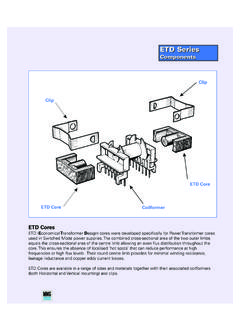
Transcription of THE FUNDAMENTALS OF CURRENT SENSE …
1 THE FUNDAMENTALS OF CURRENT SENSE TRANSFORMER DESIGN Patrick A. Cattermole, Senior Applications Engineer Abstract The following paper will first review the basic principles of operation of a CURRENT SENSE Transformer and then follow a simplified design procedure. The design procedure will take into account the effects of temperature and frequency and how they relate to the choice of a magnetic core. Introduction CURRENT SENSE transformers (CTs) are used in a variety of applications ranging from power management to precise CURRENT measurement in the automotive telecommunications, computer, industrial, consumer and medical industries. A CURRENT SENSE transformer is essentially a standard transformer whose primary is placed in series with a conductor carrying AC CURRENT . The secondary is usually terminated in a resistance and the voltage on the secondary is more or less proportional to the CURRENT in the primary.
2 Some CTs are designed to produce a voltage output which accurately tracks the AC component of the CURRENT in the primary; a linear design. Others may be designed to merely produce a change in output for a significant change in input CURRENT so that a logic device or fault circuit may be triggered. This type would not be linear. Basic Principles of Operation The equivalent circuit of a typical CURRENT transformer is shown in figure 1. Figure 1 This standard design uses an accurate and specific resistive termination on the secondary. By transformer action, the loading effect of this resistance is transferred to the primary and appears as a shunt resistance across the primary. The parallel combination of this shunt resistance and the impedance of the primary winding form the impedance through which the CURRENT flows.
3 ZsacEoutIRt MMG 10 Vansco Road, Toronto Ontario Canada THE FUNDAMENTALS OF CURRENT SENSE TRANSFORMER DESIGN Patrick A. Cattermole Typically, the transformer is designed so that the impedance of the primary winding is much greather than the shunt resistance reflected into the primary side and thus the primary impedance is mostly resistive. This shunt resistance acts as a CURRENT viewing resistor for AC CURRENT and it is this AC voltage drop that gets transferred to the secondary. It is this AC shunt resistance that the circuit sees and it is relatively easy to keep its value very low so as to have minimal effect on the circuit. Because of the isolation feature of the CURRENT SENSE transformer, it can be placed at any desired location in a circuit, including above ground, to monitor CURRENT there. Design Procedure Typical starting points, or inputs, to the design process are the following: Primary turns (Np) Sensitivity (S) Desired series AC impedance (Zsac) Maximum CURRENT rating (Imax) Minimum frequency response (fmin) Desired design results or outputs would include: Secondary turns (Ns) Secondary termination resistance (Rt) Minimum inductance factor (ALmin) The suggested design steps using the inputs listed above are as follows: 1.
4 The desired series AC impedance (Zsac) introduced into the circuit by the CURRENT transformer can be expressed in volts per ampere instead of ohms. Using this figure as the volts per ampere on the primary side of the transformer and using the desired sensitivity (S) in volts per ampere at the secondary, the turns ratio (n) is calculated. sacZSn= 2. Calculate secondary turns (Ns) using the primary turns (Np) and the turns ratio. psNnN = 3. Calculate the secondary termination resistance (Rt) using the turns ratio and the series AC impedance at the primary. 2nZRsact = THE FUNDAMENTALS OF CURRENT SENSE TRANSFORMER DESIGN Patrick A. Cattermole 4. The minimum primary inductance required (Lp) is a function of how accurate and linear the volts per ampere versus CURRENT transfer function of the transformer needs to be.
5 A good rule of thumb for an accurate and linear transformer is to design for minimum primary inductance whose inductive reactance is 100 times the primary Zsac at the minimum low frequency (fmin) design point. )2(minminfXLLp = 5. Calculate the required inductance factor to obtain the required primary inductance (Lp) with the specified number of primary turns (Np). 2minppLNLA= Design Example Following is an example of a design using the above approach: INPUT OUTPUT Primary turns (Np) = 1 Secondary turns (Ns) = 100 Sensitivity (S) = V/A Secondary termination resistance (Rt) = 50 O Series AC impedance (Zsac) = O Minimum inductance factor (ALmin) = 3981 nH/n2 Maximum CURRENT rating (Imax) = 5 A Minimum frequency response (fmin) = 20 kHz Choosing a Core Quite often, a soft ferrite toroidal core is used for a CURRENT SENSE transformer.
6 A core of surprisingly small cross section will be sufficient for CURRENT transformers handling multiple amperes at typical switch mode power frequencies. A toroidal core is well suited for a transformer with a single turn primary since it is desired to keep the primary to secondary coupling as good as possible. The toroidal core works well here because the secondary turns are completely surrounding the single primary conductor passing through the hole. Other shapes are also used, particularly at lower frequencies, where the required cross section is larger and higher numbers of both primary and secondary turns are used. As seen in the equivalent circuit in Figure 1, the primary is in shunt across the primary side series AC impedance (Zsac). If the primary is only one turn, the inductance factor of the core needs to be relatively large to provide sufficient inductive reactance at the low frequency end of the passband.
7 A toroidal shape is also efficient for this reason because the magnetic path length of a small toroid can be made small relative to the cross sectional area which will yield a high inductance factor per unit volume. THE FUNDAMENTALS OF CURRENT SENSE TRANSFORMER DESIGN Patrick A. Cattermole A high permeability material is also desirable in achieving a high inductance factor. However, one also has to take into account the required operating temperature range of the transformer. The permeability of high permeability grade materials can drop significantly with decreasing temperature. The required cross sectional area of the core is approached in essentially the same way as with any transformer. It is a function of the core material, the series AC impedance (Zsac) on the primary side, the maximum ACrms CURRENT the primary will see, and the number of primary turns.
8 It will first be necessary to calculate the maximum voltage (Ep max) that will appear across the primary. sacppZIE =maxmax For a sinusoidal AC CURRENT with no DC component, the formula relating primary voltage (Ep), turns (Np), frequency (f), and cross sectional area (Ae) is: =epeakppABNfE Solving for Ae, we have: =peakppeBNfEA As with any transformer, determining a suitable Bpeak is a function of core material and the maximum operating temperature of the transformer, as well as core losses. It is suggested to keep the maximum peak flux density at no more than 50% of the saturation flux density of the material at a particular temperature. Designing for A DC Component As with any transformer, if the CURRENT in the circuit into which the CURRENT SENSE transformer will be inserted has a DC component, it must be taken into account in the transformer design.
9 The DC component of the CURRENT in the primary will produce a DC component of flux density in the core material. An equation for calculating the approximate value of the DC component of flux density is as follows: peakHpeakBdcedc = Where: edcpdclpeakINH = 4 THE FUNDAMENTALS OF CURRENT SENSE TRANSFORMER DESIGN Patrick A. Cattermole The units are B in gauss, I in amperes, le (the magnetic path length of the core ) in mm, and H in oersteds. This is only an approximation because the permeability of the core material will decrease as DC CURRENT increases. The e in the Bdc formula above is the effective permeability of the magnetic circuit of the transformer. Of course, if an ungapped toroid core is used, the effective permeability is the permeability of the material. On the plus side, usually the primary of a CURRENT SENSE transformer has a small number of turns.
10 Since Hdc is proportional to turns, this is desirable. A gapped ferrite core or powdered metal core may be required for situations with high DC components. Frequency Response As has already been discussed, the low frequency rolloff of the transformer is a function of the primary inductance. A high inductance factor core is desired because of the low number of primary turns. As the inductive reactance of the primary decreases with decreasing frequency, it will effectively shunt an excessive amount of CURRENT away from the series AC CURRENT SENSE impedance as frequency decreases. As for the high frequency rolloff of a CURRENT SENSE transformer, there are both positives and negatives to this type of design. On the positive side, coupling between primary and secondary is usually good, so leakage inductance is relatively low.