Transcription of THE GMC MOTORHOME STEERING BOX
1 THE GMC MOTORHOME STEERING BOX By Don Wirth Theory of operation The Saginaw power STEERING box is a hydraulically assisted mechanical rack and pinion STEERING system different only in that the rack drives the pinion rather than normal where the pinion drives the rack. The rack is also the hydraulic piston that moves the STEERING geometry. It is mechanically driven by a 7/16 pitch lead ball screw. This ball screw is mechanically driven by the STEERING wheel. Between the STEERING wheel and the ball screw is a complex hydraulic valve with many ports for both left and right movements. When turning left or right the hydraulic oil is directed to the piston (rack) and at the same time a small torsion bar inside the stub shaft is winding up. As the STEERING wheel is relaxed the torsion bar unwinds and closes the hydraulic valve to relieve the force on the piston and the box will hold in the curve position until you move the STEERING wheel to a new curve or straight ahead position.
2 The valve ports are held in a new port closed location when in a turn. All boxes have this torsion bar. For additional, and more detailed, information on the operation of the STEERING box refer to the service manual. Identifying the proper STEERING box The power STEERING box used in the GMC motorhomes was built by Saginaw and was used on most General Motors vehicles in the decades of the 60 s, 70 s and 80 s as well as some Ford and Chrysler vehicles. There are several versions of this gearbox. For clarity, I will address only those that are usable in the GMC Motor home. In the 60 s, 70 s, and 80 s there are only two castings that fit our requirements. The truck box that I will call left hand is mounted on the outside of the frame. The car box is right hand and is mounted on the inside of the frame. Although they look very similar they are left and right castings and the car box casting cannot be used in the GMC MOTORHOME . However all the inside components of the car box are the same as the truck and can be used.
3 Torsion bar from inside the stub shaft MOTORHOME end plug with extended boss and spacer to limit movement GMC MOTORHOME STEERING box All trucks 1/2-3/4-1&1-1/2 ton GMCs also several Dodge and a few Ford trucks. All full size GM cars. Trucks 3/4 and above have no internal added stops and yield 4-1/4 turns lock to lock. When these same boxes are used in the 1/2 Ton truck and our GMC a spacer is inserted at the top of the stroke and the bottom aluminum pug has a extended boss. These two items restrict the movement to 3-1/3 turns lock to lock as in our GMC s. Also, truck boxes may have a stub on the input shaft. No problem, just cut it off. Some muscle cars in the late 70s offered 2-1/2 turns lock to lock. These car parts can be used in our MH. However, It gives stiffer STEERING and more effort to park. This change in STEERING ratio is done by changing the pitch of the lead on the ball screw from 7/16 to 9/16 . I will cover these mechanics later.
4 Metric components started in 1984. While these late model STEERING boxes will bolt into the chassis, you need to change the way the power STEERING fluid connections are made. Adapters to convert the metric fluid connection lines to earlier standard fittings are available. The newer boxes use an o-ringed metric end while the older boxes use the common 3/8" flare end. NAPA sells the required adapters. They are: Weatherhead #1445: 3/8" is 5/8 18 - Weatherhead #1446: 3/8" is 5/8 18 - Weatherhead #1447: 3/8" is 5/8 18 - An alternative and simple way of dealing with the metric hoses if you get the box in a wrecking yard is to keep about six inches of the metric power STEERING hoses with the box. On installation cut off six inches of your original hose and then connect your original hose to the metric hose with a tube coupling. The tube diameters are close enough to do this. I use Swage-lock fittings and it will pull down just fine. This information about metric threads applies to the late model STEERING gear like that being sold by Cinnabar.
5 In Summary, To find the correct box Any GMC truck 1960-1980. If you are away from home the big truck box can be used as is; just be careful in a tight turn to stop turning when you reach the suspension stops. The Lead screw on the top was used for quick turning muscle cars. The 7/16 pitch lead screw on the bottom is what is used on trucks and GMC motorhomes. Stub on the input shaft on some truck boxes. Just cut it off. The 3/4 ton and above, to conform 100% to the MH, will need the internal spacer from your box installed and your extended boss bottom aluminum plug used in place of the truck plug. If you just wish to rebuild your present unit you can use internal components from any full size GM car 1960-1980. However, the input shaft must be a 3/4" 24-point spline (use a 3/4" 12-point socket to confirm). And the pitman shaft (output shaft) must have a tapered splined end with lock washer and nut as used on our GMC s. Most trucks and cars will have these features.
6 Removing the STEERING box from your GMC Remove and cap the power STEERING hoses, remove the bolt securing the STEERING shaft to the input shaft, remove either the pitman arm from the output shaft or the drag link from the pitman arm. I recommend that the pitman arm be separated from the drag link rather than from the STEERING box. Remove the four bolts holding the box to the frame. Don t drop it on yourself, it s heavier than it looks. Disassembly The valve cartridge is a removable part but has very limited repair possibilities. It can be removed by taking off the lock nut and with a spanner wrench backing the cartridge out of the STEERING box. The removable parts are the roller thrust bearing in the bottom, the top bearing, and the seal at the top. Earlier models also had a dust shield, which is now not available except in a seal kit. Powercraft has a kit for these parts Part # 7095. Seals are also available at bearing houses. Normally the input shaft seal will be the only part needed.
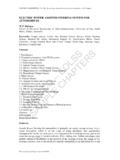
7 The seal and the bearing at the output pitman shaft can be replaced, however the movement of the output shaft is so small they hold up forever. Bottom line, for normal rework and setting up a gearbox only the top seal needs to be replaced. If you want to just replace the input shaft seal this can be done with the box still on the coach. Remove the left front wheel and inner wheelhouse, the STEERING shaft at the input MOTORHOME end plug on the left, truck end plug on the right Using a 12 point socket to identify proper input shaft for the GMC MOTORHOME Correct output shaft with tapered spline, lock washer and nut Powercraft 7095 upper seal kit shaft, the seal retaining snap ring, and the dust cover if used. This will expose the top of the seal, which can be pierced and pulled out with probe tools or a small slide hammer. If you do remove the rack piston and the balls fall out you will find that there are black & silver balls, which are.
8 0005 different in diameter. When reinstalling the balls, alternate the colors. 18 balls will go into the rack piston; the other 6 go into the return guide. Hold the balls in place in the return guide with Vaseline do not use heavier grease. STEERING box adjustment The only way to properly adjust the STEERING box is to remove it from the vehicle. Tools required: Inch pound torque wrench capable of readings under 20 inch pounds, Spanner wrench. 5/8 end wrench to loosen the pitman shaft adjusting screw lock nut, 3/16 Allen wrench to turn the pitman shaft adjusting screw The setting up of the gearbox is quite simple using an inch pound torque wrench. Note: Most click type inch pound torque wrenches only work above 20 in/lbs this is too high for our purposes. 1) Adjust the valve cartridge preload. The pitman shaft adjustment screw and lock nut must be completely backed off by loosening the retaining nut and turning the Allen screw counterclockwise a few turns.
9 Pump the power STEERING fluid from the inside of the box by moving the pitman arm back and forth. Loosen the adjuster plug locknut and, using a spanner wrench, screw down the adjuster plug cartridge until you get about four (4) in/lbs of preload measured at the input shaft. Then lock it down with the lock nut. 2) Find the center of the movement by turning the input shaft halfway through the total movement. To verify, when centered the plane of the machined surface of the side adjustment plate will be parallel to, and in the same plane as, the flat spot on the input shaft. 3) With the in/lb torque wrench turning the input shaft a few degrees from center in both directions turn the pitman shaft Allen adjustment screw until you read another 10 in/lbs to see a total of 14 in/lbs at top dead center. These numbers are nominal and could be slightly more or less. Using an inch-pound torque wrench to measure preload The alignment of these two machined surfaces is mandatory (top dead center), and must be held when installing the box on the vehicle.
10 This is important because the 10 in/lbs tight spot is only in contact for about 8 to 10 degrees of STEERING wheel movement in ether direction. If this true center is not maintained, you will have magnified movement through the STEERING system due to the machined clearance of the teeth of the rack and pinion without preload. Having the box on center and the wheels straight ahead is sometime difficult to do in an old system unless you have an after market adjustable pitman arm. Summary Well, there you have it. The STEERING box should no longer be a mystery and great STEERING should be yours soon. Just find someone to do a good 6-wheel alignment for you. Make SURE they keep the STEERING box centered! DISCLAIMER: Information presented by GMCES is intended only to communicate thoughts, ideas, opinions and procedures to and from GMC owners; there is no attempt to replace or supersede recommendations from General Motors Corporation or any other component manufacturer.