Transcription of The “Hairpin” Match - ehpes
1 The Hairpin MatchA hairpin Match is a simple impedance transforming method that can sometimes be used to Match low impedance Yagis, short antennas, and others, to higher impedance feed linesBill Wortman, N6 MWIntroductionExperimental antennas often do not immediately appear with a 50 ohm input that will provide a 1:1 SWR by just attaching your standard feed line. Numerous approaches are discussed to adding various matching devices at the antenna to cure this problem in the ham literature. Often the discussions of such methods do not dwell the question of how you start to make a selection of a matching method but just provide a solution for the author s example. In this article the simple and often cited1,2,3 matching method often called hairpin matching will be discussed to help determine if a hairpin Match can meet your needs, andindicate how to design and implement that Match .
2 Hairpin matching is nothing more than adding an inductance directly across the feed point of the antenna . The inductance may be a simple wire coil or an extended U-shaped wire or rods. This U-shape is of course the reason for the name hairpin and many applications of this matching style use that form of inductance. Sometimes this method iscalled shunt matching, but beware because other forms of matching also use the word shunt although some are rather might ask why not use hairpin matches all the time since they are so simple. Unfortunately simplicity goes hand-in-hand with limited applicability and dealing with this is the key to matching is Matching Needed?The object of the game is to get as much of your transmitter s power as possible to exit the antenna as RF radiation.
3 If your transmitter, with its ability to Match a nominal 50 ohm impedance, is well matched to the input impedance at the feed line, this transfer efficiency will be maximized. If the feed line has a SWR near 1:1, the ohmic losses in the feed line will be minimized to produce the best signal efficiency. As a result, operators attempt to have antennas with an input impedance near 50 ohms and then generally use coaxial cable with a characteristic impedance near 50 ohms. Of course, there is nothing wrong with using open wire feed reason for good matching is sometimes more practical. With a mismatched transmitter and antenna plus feed line system, some transmitters and amplifiers balk when presented with a higher SWR that is not to their liking.
4 This can result in automatically reduced power output, or even shut down, to prevent damage. If you have a transmitter with an antenna tuning unit (ATU) or an outboard antenna tuner (really impedance matching networks) the only remaining potential source of loss is from a high SWR from the feed line mismatch to the antenna , which generally becomes important only for large SWR, long cable runs and higher frequencies. In any case, life is generallybetter if your antenna input impedance, after matching, is in the neighborhood of 50 ohmsalthough concern about getting very low SWR is sometimes overrated. However, with resonant antennas and no tuner, a low SWR at its minimum value will give the largest bandwidth with a manageable SWR.
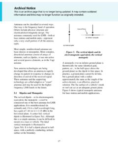
5 How Hairpin Impedance Transformation WorksIf an antenna has an unmatched complex impedance of Za (Ra+jXa), adding an inductance across the antenna input (sometimes loosely referred to as a shunt ) gives an equivalent circuit as shown in the figure, where Ro+jXo is the resulting transformed complex impedance output. The object is then to select the added inductance value to cause Ro to be close to the feed line characteristic impedance (often 50 ohms) with the net output reactance Xo near 1. Schematic of hairpin addition and the equivalent adding just one inductance of our choice, you want to both get Ro to be near the feed line impedance and make Xo be near zero. You might wonder if it is possible to do both with just one additional component.
6 The answer is generally no. However, if Za has one of a range of appropriate values, it will equation that describes this parallel circuit is not difficult, although some may be put off by the need to deal with complex numbers. This is expanded on in the sidebar. The upshot is if Ra is less than Ro, there is always a capacitive Xa (negative) and a hairpin inductance XL that will produce a perfect +j XoHairpin (XL)At first blush you might think if I just short out the antenna input with a bit of wire, won tmuch of the current coming up the feed line just go through the added wire and not the antenna - and that won t be so good. It turns out that the magnitude of the current in the hairpin is generally comparable with that in Za, and it can be larger than the feed line current.
7 This is because the hairpin and Za currents are far from being in phase. But it turns out that this delicate balance makes the hairpin matched antenna appear as an impedance of Ro, even though there are (mostly) non-radiating currents in the hairpin . How To Design A Hairpin MatchThe first requirement for use of the hairpin is that the unmatched antenna resistive part, Ra, must be significantly less than the desired feed line impedance, Ro. Second, the unmatched antenna reactive part, Xa, must be capacitive (negative) and also must be nearthe required value calculated in the sidebar. Xa can often be adjusted by modest changes in the length of the driven element or by addition of loading.
8 Once the appropriate Xa is available, there is a hairpin inductive reactance, XL, that can provide a perfect Match . Sometimes getting a perfect Match is out of practical reach, primarily due to lack of knowledge or control of the unmatched antenna impedance. However, the Match does not need to be perfect to be useful. It can be helpful to have the design information available in graphical form. With these things in mind, the following two pairs of plots show first contours of the best SWR that can be produced by a hairpin Match for a wide range of Ra and Xa values, provided you have the right XL, and the second provides that optimal XL value as contours for all the Ra and Xa pairs. The black line is the SWR=1:1 curve corresponding to the perfect Match equations in the sidebar.
9 The first pair is for a target feed line impedance of 50 ohms and the second pair is for a target of 200 ohms. The plots appear similar but the scales for the two are different. Note that the SWR changes only slowly with Xa and XL so great accuracy in their selection is not 2. Plots of (a) SWR and (b) XL for hairpin matching to a 50 ohm (ohm)Ra (ohm)Xa (ohm)XL for 50 ohm lineSWRRa (ohm)Xa (ohm)SWR for 50 ohm lineFigure 3. Plots of (a) SWR and (b) XL for hairpin matching to a 200 ohm plots can be used to design a hairpin Match by using your measured or calculated Ra,then finding the corresponding required Xa along the 1:1 SWR curve. Then go to the XLcurve to find the needed hairpin inductance.
10 Finally adjust your antenna to have the needed Xa and apply the required inductor across the feed point. The inductor might be asimple coil or hairpin shaped unit. These results for Ra are essentially the same as provided in the plots in the Note 2 reference, but the value of Xa is now available. As has been pointed out by a number of other authors, matching by use of a capacitive shunt for a positive Xa (inductive) case is really the same except for the change of signs of Xa and XL. However, the use of capacitors as shunt components presents other for Hairpin Shaped InductanceA hairpin shape of two parallel conductors with a shorting bar , perhaps adjustable, at the end can be viewed as a shorted transmission line.