Transcription of The High Performance Company - Aaron Simms
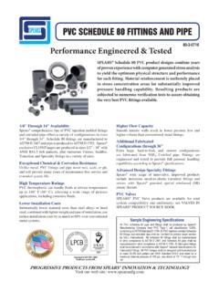
1 TheHighPerformanceCompany RESILIENT SEATEDSERIES 30/31 Wafer/Lug2"- 20" (50mm-500mm)BUTTERFLY VALVESCELEBRATINGYEARSBCEFGGHIJKSERIES 302" 20" (50mm 500mm) Bray Controls is proud to offer a high quality line of butterfly valves to meet the requirements of today s market. Combining years of field application experience, research and development, Bray has designed many unique features in the Series 30/31 not pre-viously available. The results are longer service life, greater reliability, ease of parts replace-ment and interchangeability of components. DISC AND STEM CONNECTION (A) Features a high -strength through stem design. The close tolerance, double D connection that drives the valve disc is an exclusive feature of the Bray valve.
2 It eliminates stem retention components being exposed to the line media, such as disc screws and taper pins, which com-monly result in leak paths, corrosion, and vibration failures. Disc screws or taper pins, due to wear and corrosion, often Double D Connection require difficult machining for disassem-bly. Disassembly of the Bray stem is just a matter of pulling the stem out of the disc. Without fasteners obstructing the line flow, the Series 30/31 Cv values are higher than many other valves, turbulence is reduced, and pressure recovery is increased. The stem ends and top mounting flange are standardized for interchangeability with Bray actuators. DISC (B) Casting is spherically machined and hand polished to provide a bubble-tight shut off, minimum torque, and longer seat life.
3 The disc clearance is designed to work with all standard piping. D A STEM RETAINING ASSEMBLY (C) The stem is retained in the body by means of a unique Stainless Steel Spirolox retaining ring, a thrust washer and two C-rings, manufactured from brass as standard, stainless steel upon request. The retaining ring may be easily removed with a standard hand tool. The stem retaining assembly prevents unintentional removal of the stem during field service. Stem Retaining Spirolox Retaining Ring Thrust Washer C-Rings STEM BUSHING (D) Non-corrosive, heavy duty acetal bushing absorbs actuator side thrusts. STEM SEAL (E) Double U cup seal design is self-adjusting and gives positive sealing in both direc-tions. Prevents external substances from entering the stem bore.
4 NECK (F) Extended neck length allows for 2" of piping insulation and is easily acces-sible for mounting actuators. PRIMARY AND SECONDARY SEALS (G) The Primary Seal is achieved by an interference fit of the molded seat flat with the disc hub. The Secondary Seal is created because the stem diameter is greater than the diameter of the seat stem hole. These seals prevent line media from coming in contact with the stem or body. BRAY UNIQUE SEAT DESIGN (H) One of the valve s key elements is Bray s unique tongue and groove seat design. This resilient seat features lower torque than many valves on the market today and provides complete isolation of flowing media from the body. The tongue-and-groove seat to body retention method is superior to traditional designs, making field replacement simple and fast.
5 The seat is specifically designed to seal with slip-on or weld-neck flanges. The seat features a molded O-ring which eliminates the use of flange gaskets. An important maintenance feature is Tongue and Groove Design * Spirolox designation is a registered trademark of Kaydon Ring and Seal, Inc. that all resilient seats for Bray butterfly valves Series 20, 21, 30, 31 and 34 are completely interchangeable. ACTUATOR MOUNTING FLANGE AND STEM CONNECTION (I) Universally designed to ISO 5211 for direct mounting of Bray power actuators and manual operators. FLANGE LOCATING HOLES (J) Provide quick and proper alignment during installation. BODY (K) One-piece wafer or lug style. Polyester coating for excellent corrosion resistance. Bray valve bodies meet ANSI 150 pressure ratings for hydrostatic shell test requirements.
6 DESIGN FEATURES Bray s Series 30 valve is a wafer version with flange locating holes, and the Series 31 is the companion lug version for dead-end service and other flange require ments. All Bray valves are tested to 110% of full pressure rating before shipment. A major design advantage of Bray valve product lines is international compati bility. The same valve is compatible with most world flange standards ANSI Class 125/150, BS 10 Tables D and E, BS 4504 NP 10/16, DIN ND 10/16, AS 2129 and JIS10. In addition the valves are designed to comply with ISO 5752 face-to-face and ISO 5211 actuator mounting flanges. Therefore, one valve design can be used in many different world markets. Due to a modular concept of design, all Bray handles, manual gear operators and pneumatic and POLYESTER COATING CORROSION PROTECTION Bray s standard product offers valve bodies with a polyester coat-ing, providing excellent corrosion and wear resistance to the valve s surface.
7 The Bray polyester coating is a hard, gloss red finish. Chemical Resistance resists a broad range of chemicals including: dilute aqueous acids and alkalies, petroleum solvents, alcohols, greases and oils. Offers outstanding resistance to humidity and water. Weatherability outdoor tested resistant to ultra-violet radiation. Abrasion Resistance excellent resistance to abrasion. Impact Resistance withstands impact without chipping or cracking. NYLON 11 COATING Optionally available for valve bodies where outstanding protection and Performance is needed. A thermoplastic produced from a vegetable base, this coating is inert to fungus growth and molds. Nylon 11 is USDA Approved, as well as certified to ANSI/NSF 61 for water service.
8 Corrosion Resistance superior resistance to a broad range of chemical environ ments. Salt spray tested in excess of 2,000 hours and seawater immersion tested for over 10 years without corrosion to metal substrates. Nylon 11 features a very low coefficient of friction and excellent resistance to impact and ultra-violet radiation. SERIES 31 Lug electric actuators mount directly to Bray valves. No brackets or adapters are required. Bray interchangeability and compatibility offers you the best in uniformity of product line and low-cost Performance in the industry today. DIMENSIONS SERIES 30 Wafer BC Lug Valve Valve Size Mounting Flange Drig. GH J Kins mm AB C D E F BC No. Holes Hole Dia. 2 50 4 .39 .55 .39 21/2 65 4.
9 39 .55 .39 3 80 4 .39 .55 .39 4 100 4 .39 .63 .43 5 125 4 .39 .75 .51 6 150 4 .39 .75 .51 8 200 4 .57 .87 .63 10 250 4 .57 .87 12 300 4 .57 .87 Lug Bolting Data BC No. Holes Threads UNC-2B 4 5/8-11 4 5/8-11 4 5/8-11 8 5/8-11 8 3/4-10 8 3/4-10 8 3/4-10 12 7/8-9 12 7/8-9 Valve Size Mounting Flange Drig. GJ KEY SIZE Kins mm AB C D E F BC No. Holes Hole Dia. 14 350 4 .57 . 16 400 4 .57 . 18 450 4 .81 . 20 500 4 .81 . Lug Bolting Data BC No. Holes Threads UNC-2B 12 1-8 16 1-8 16 1 1/8-7 20 1 1/8-7 See chart for Actuator Mounting Flange Drilling.
10 SELECATATION DFLANGE REQUIREMENTS Bray valves are designed for installation between ANSI Class 125/150 lb. weld-neck or slip-on flanges, BS 10 Tables D & E, BS 4504 NP 10/16, DIN ND 10/ 16, AS 2129 and JIS 10, either flat faced or raised faced. While weld-neck flanges are recom mended, Bray has specifically designed its valve seat to work with slip-on flanges, thus eliminating common failures of other butterfly valve designs. When using raised face flanges be sure to properly align valve and flange. Type C stub-end flanges are not recommended. Cv VALUES VALVE SIZING COEFFICIENT Valve Size Disc Position (degrees) ins mm 90 80 70 60 50 40 30 20 10 2 50 144 114 84 61 43 27 16 7 1 21/2 65 282 223 163 107 67 43 24 11 3 80 461 364 267 154 96 61 35 15 2 4 100 841 701 496 274 171 109 62 27 3 5 125 1376 1146 775 428 268 170 98 43 5 6 150 1850 1542 1025 567 354 225 129 56 6 8 200 3316 2842 1862 1081 680 421 241 102 12 10 250 5430 4525 2948 1710 1076 667 382 162 19 12 300 8077 6731 4393 2563 1594 1005 555 235 27 14 350 10538 8874 5939 3384 2149 1320 756 299 34 16 400 13966 11761 7867 4483 2847 1749 1001 397 45 18 450 17214 14496 10065 5736 3643 2237 1281 507 58 20 500 22339 18812 12535 7144 4536 2786 1595 632 72 Slip-OnWeld-Neck PRESSURE RATINGS* For bi-directional bubble-tight shut off, disc in closed position.