Transcription of The Horizontal Directional Drilling Process
1 APPENDIX J Horizontal Directional Drilling The Horizontal Directional Drilling Process The tools and techniques used in the Horizontal Directional Drilling (HDD) Process are an outgrowth of the oil well Drilling industry. The components of a Horizontal Drilling rig used for pipeline construction are similar to those of an oil well Drilling rig with the major exception being that a Horizontal Drilling rig is equipped with an inclined ramp as opposed to a vertical mast. HDD pilot hole operations are not unlike those involved in Drilling a Directional oil well.
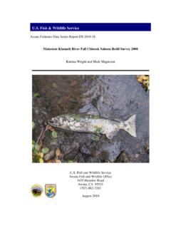
2 Drill pipe and downhole tools are generally interchangeable and Drilling fluid is used throughout the operation to transport drilled spoil, reduce friction, stabilize the hole, etc. Because of these similarities, the Process is generally referred to as Drilling as opposed to boring. Installation of a pipeline by HDD is generally accomplished in three stages as illustrated in Figure 1. The first stage consists of directionally Drilling a small diameter pilot hole along a designed Directional path. The second stage involves enlarging this pilot hole to a diameter suitable for installation of the pipeline.
3 The third stage consists of pulling the pipeline back into the enlarged hole. Pilot Hole Directional Drilling Pilot hole Directional control is achieved by using a non-rotating drill string with an asymmetrical leading edge. The asymmetry of the leading edge creates a steering bias while the non-rotating aspect of the drill string allows the steering bias to be held in a specific position while Drilling . If a change in direction is required, the drill string is rolled so that the direction of bias is the same as the desired change in direction. The direction of bias is referred to as the tool face.
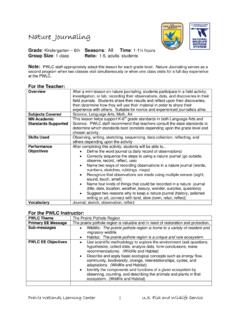
4 Straight progress may be achieved by Drilling with a series of offsetting tool face positions. The drill string may also be continually rotated where Directional control is not required. Leading edge asymmetry can be accomplished by several methods. Typically, the leading edge will have an angular offset created by a bent sub or bent motor housing. This is illustrated schematically in Figure 2. It is common in soft soils to achieve Drilling progress by hydraulic cutting with a jet nozzle. In this case, the direction of flow from the nozzle can be offset from the central axis of the drill string thereby creating a steering bias.
5 This may be accomplished by blocking selected nozzles on a standard roller cone bit or by custom fabricating a jet deflection bit. If hard spots are encountered, the drill string may be rotated to drill without Directional control until the hard spot has been penetrated. Drilling FLUID RETURNSANNULUSDESIGNED DRILLED PATHDRILL PIPEEXIT POINTENTRY POINTHORIZONTAL Drilling RIGPILOT HOLEPREREAMINGDRILL PIPETYPICAL DIRECTION OF PROGRESSDIRECTION OF PROGRESSDIRECTION OF PROGRESSPULLBACKDRILL PIPEDRILL PIPEPREFABRICATED PULL SECTIONANNULUSANNULUSDRILLING FLUID RETURNSDRILLING FLUID RETURNS Figure 1 The HDD Process STEERING TOOLBITMUD MOTORORIENTING SUBNON-MAGNETIC COLLARBENT MOTOR HOUSINGANGULAROFFSET Figure 2 Bottom Hole Assembly Downhole Motors Downhole mechanical cutting action required for harder soils is provided by downhole
6 Hydraulic motors. Downhole hydraulic motors, commonly referred to as mud motors, convert hydraulic energy from Drilling mud pumped from the surface to mechanical energy at the bit. This allows for bit rotation without drill string rotation. There are two basic types of mud motors; positive displacement and turbine. Positive displacement motors are typically used in HDD applications. Basically, a positive displacement mud motor consists of a spiral-shaped stator containing a sinusoidal shaped rotor. Mud flow through the stator imparts rotation to the rotor which is in turn connected through a linkage to the bit.
7 In some cases, a larger diameter wash pipe may be rotated concentrically over the non-rotating steerable drill string. This serves to prevent sticking of the steerable string and allows its tool face to be freely oriented. It also maintains the pilot hole if it becomes necessary to withdraw the steerable string. Downhole Surveying The actual path of the pilot hole is monitored during Drilling by taking periodic readings of the inclination and azimuth of the leading edge. Readings are taken with an instrument, commonly referred to as a probe, inserted in a drill collar as close as possible to the drill bit.
8 Transmission of downhole probe survey readings to the surface is generally accomplished through a wire running inside the drill string. These readings, in conjunction with measurements of the distance drilled since the last survey, are used to calculate the Horizontal and vertical coordinates along the pilot hole relative to the initial entry point on the surface. Azimuth readings are taken from the earth's magnetic field and are subject to interference from downhole tools, drill pipe, and magnetic fields created by adjacent structures. Therefore, the probe must be inserted in a non magnetic collar and positioned in the string so that it is adequately isolated from downhole tools and drill pipe.
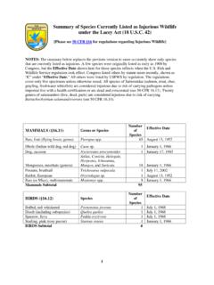
9 The combination of bit, mud motor (if used), subs, survey probe, and non magnetic collars is referred to as the Bottom Hole Assembly or BHA. A typical bottom hole assembly is shown as Figure 2. Surface Monitoring The pilot hole path may also be tracked using a surface monitoring system. Surface monitoring systems determine the location of the probe downhole by taking measurements from a grid or point on the surface. An example of this is the TruTracker System. This system uses a surface coil of known location to induce a magnetic field. The probe senses its location relative to this induced magnetic field and communicates this information to the surface.
10 This is shown schematically in Figure 3. SURFACE COILKNOWN CORNER LOCATIONSSURVEYPROBE Figure 3 TruTracker Surface Monitoring System Reaming & Pullback Enlarging the pilot hole is accomplished using either prereaming passes prior to pipe installation or simultaneously during pipe installation. Reaming tools typically consist of a circular array of cutters and Drilling fluid jets and are often custom made by contractors for a particular hole size or type of soil. Prereaming Most contractors will opt to preream a pilot hole before attempting to install pipe. For a prereaming pass, reamers attached to the drill string at the exit point are rotated and drawn to the Drilling rig thus enlarging the pilot hole.