Transcription of THE I2C-BUS SPECIFICATION VERSION 2.1 JANUARY 2000
1 THE I 2C-BUS SPECIFICATIONVERSION 2000document order number: 9398 393 40011 2 Philips Semiconductors The I2C-BUS specificationCONTENTS1 PREFACE .. - 1992.. - 198.. - 1999.. of Philips I2C-BUS components .. 32 THE I2C-BUS BENEFITS DESIGNERS AND MANUFACTURERS .. benefits .. benefits .. 63 INTRODUCTION TO THE I2C-BUS SPECIFICATION .. 64 THE I2C-BUS CONCEPT .. 65 GENERAL CHARACTERISTICS .. 86 BIT TRANSFER .. validity .. and STOP conditions .. 97 TRANSFERRING DATA .. format .. 108 ARBITRATION AND CLOCK GENERATION .. of the clock synchronizing mechanism as a handshake .. 139 FORMATS WITH 7-BIT ADDRESSES .. 13107-BIT ADDRESSING .. of bits in the first byte .. call address .. byte .. compatibility .. 1811 EXTENSIONS TO THE STANDARD-MODE I2C-BUS SPECIFICATION .. 1912 FAST-MODE .. 1913Hs-MODE.
2 Speed transfer.. data transfer format in Hs-mode .. from F/S- to Hs-mode and back .. devices at lower speed modes .. speed modes on one serial bus system .. transfer in a mixed-speed bus system .. transfer in a mixed-speed bus system .. requirements for the bridge in a mixed-speed bus system .. 271410-BIT ADDRESSING .. of bits in the first two bytes.. with 10-bit addresses.. call address and start byte with 10-bit addressing .. 3015 ELECTRICAL SPECIFICATIONS AND TIMING FOR I/O STAGES AND BUS LINES .. and Fast-mode devices.. devices .. 3416 ELECTRICAL CONNECTIONS OF I2C-BUS DEVICES TO THE BUS LINES . and minimum values of resistors Rp and Rs for Standard-modeI2C-bus devices .. 3917 APPLICATION INFORMATION .. output stages of Fast-mode I2C-BUS devices .. pull-up circuit for Fast-mode I2C-BUS devices.
3 Pattern of the bus lines .. and minimum values of resistors Rp and Rs for Fast-mode I2C-BUS devices .. and minimum values of resistors Rp and Rs for Hs-mode I2C-BUS devices .. 4218BI-DIRECTIONAL LEVEL SHIFTER FOR F/S-MODE I2C-BUS SYSTEMS .. devices with different logic levels .. of the level shifter .. 4419 DEVELOPMENT TOOLS AVAILABLE FROM PHILIPS .. 4520 SUPPORT LITERATURE .. 46 3 Philips Semiconductors The I2C-BUS - 1992 This VERSION of the 1992 I2C-BUS SPECIFICATION includes the following modifications: Programming of a slave address by software has been omitted. The realization of this feature is rather complicated and has not been used. The low-speed mode has been omitted. This mode is, in fact, a subset of the total I2C-BUS SPECIFICATION and need not be specified explicitly. The Fast-mode is added. This allows a fourfold increase of the bit rate up to 400 kbit/s.
4 Fast-mode devices are downwards compatible they can be used in a 0 to 100 kbit/s I2C-BUS system. 10-bit addressing is added. This allows 1024 additional slave addresses. Slope control and input filtering for Fast-mode devices is specified to improve the EMC : Neither the 100 kbit/s I2C-BUS system nor the 100 kbit/s devices have been - 1998 The I2C-BUS has become a de facto world standard that is now implemented in over 1000 different ICs and licensed to more than 50 companies. Many of today s applications, however, require higher bus speeds and lower supply voltages. This updated VERSION of the I2C-BUS SPECIFICATION meets those requirements and includes the following modifications: The High-speed mode (Hs-mode) is added. This allows an increase in the bit rate up to Mbit/s. Hs-mode devices can be mixed with Fast- and Standard-mode devices on the one I2C-BUS system with bit rates from 0 to Mbit/s.
5 The low output level and hysteresis of devices with a supply voltage of 2 V and below has been adapted to meet the required noise margins and to remain compatible with higher supply voltage devices. The V at 6 mA requirement for the output stages of Fast-mode devices has been omitted. The fixed input levels for new devices are replaced by bus voltage-related levels. Application information for bi-directional level shifter is - 2000 VERSION of the I2C-BUS SPECIFICATION includes the following minor modifications: After a repeated START condition in Hs-mode, it is possible to stretch the clock signal SCLH (see Section and Figs 22, 25 and 32). Some timing parameters in Hs-mode have been relaxed (see Tables 6 and 7). of Philips I2C-BUS componentsPurchase of Philips I2C components conveys a license under the Philips I2C patent to use the components in the I2C system provided the system conforms to the I2C SPECIFICATION defined by Philips.
6 4 Philips Semiconductors The I2C-BUS specification2 THE I2C-BUS BENEFITS DESIGNERS AND MANUFACTURERSIn consumer electronics, telecommunications and industrial electronics, there are often many similarities between seemingly unrelated designs. For example, nearly every system includes: Some intelligent control, usually a single-chip microcontroller General-purpose circuits like LCD drivers, remote I/O ports, RAM, EEPROM, or data converters Application-oriented circuits such as digital tuning and signal processing circuits for radio and video systems, or DTMF generators for telephones with tone dialling. To exploit these similarities to the benefit of both systems designers and equipment manufacturers, as well as to maximize hardware efficiency and circuit simplicity, Philips developed a simple bi-directional 2-wire bus for efficient inter-IC control.
7 This bus is called the Inter IC or I2C-BUS . At present, Philips IC range includes more than 150 CMOS and bipolar I2C-BUS compatible types for performing functions in all three of the previously mentioned categories. All I2C-BUS compatible devices incorporate an on-chip interface which allows them to communicate directly with each other via the I2C-BUS . This design concept solves the many interfacing problems encountered when designing digital control are some of the features of the I2C-BUS : Only two bus lines are required; a serial data line (SDA) and a serial clock line (SCL) Each device connected to the bus is software addressable by a unique address and simple master/slave relationships exist at all times; masters can operate as master-transmitters or as master-receivers It s a true multi-master bus including collision detection and arbitration to prevent data corruption if two or more masters simultaneously initiate data transfer Serial, 8-bit oriented, bi-directional data transfers can be made at up to 100 kbit/s in the Standard-mode, up to 400 kbit/s in the Fast-mode, or up to Mbit/s in the High-speed mode On-chip filtering rejects spikes on the bus data line to preserve data integrity The number of ICs that can be connected to the same bus is limited only by a maximum bus capacitance of 400 1 shows two examples of I2C-BUS benefitsI2C-bus compatible ICs allow a system design to rapidly progress directly from a functional block diagram to a prototype.
8 Moreover, since they clip directly onto the I2C-BUS without any additional external interfacing, they allow a prototype system to be modified or upgraded simply by clipping or unclipping ICs to or from the are some of the features of I2C-BUS compatible ICs which are particularly attractive to designers: Functional blocks on the block diagram correspond with the actual ICs; designs proceed rapidly from block diagram to final schematic. No need to design bus interfaces because the I2C-BUS interface is already integrated on-chip. Integrated addressing and data-transfer protocol allow systems to be completely software-defined The same IC types can often be used in many different applications Design-time reduces as designers quickly become familiar with the frequently used functional blocks represented by I2C-BUS compatible ICs ICs can be added to or removed from a system without affecting any other circuits on the bus Fault diagnosis and debugging are simple.
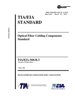
9 Malfunctions can be immediately traced Software development time can be reduced by assembling a library of reusable software addition to these advantages, the CMOS ICs in the I2C-BUS compatible range offer designers special features which are particularly attractive for portable equipment and battery-backed all have: Extremely low current consumption High noise immunity Wide supply voltage range Wide operating temperature range. 5 Philips Semiconductors The I2C-BUS Two examples of I2C-BUS applications: (a) a high performance highly-integrated TV set (b) DECT cordless phone , full pagewidthSDASCLMICRO-CONTROLLERPCB83C528 PLLSYNTHESIZERTSA5512 NON-VOLATILEMEMORYPCF8582 ESTEREO / DUALSOUNDDECODERTDA9840HI-FIAUDIOPROCESS ORTDA9860 SINGLE-CHIPTEXTSAA52 XXM/S COLOURDECODERTDA9160 APICTURESIGNALIMPROVEMENTTDA4670 VIDEOPROCESSORTDA4685ON-SCREENDISPLAYPCA 8510(a)MSB575 SDASCLLINEINTERFACEPCA1070 BURST MODECONTROLLERPCD5042 ADPCMPCD5032(b)DTMFGENERATORPCD3311 MICRO-CONTROLLERP80 CLXXX 6 Philips Semiconductors The I2C-BUS benefitsI2C-bus compatible ICs don t only assist designers, they also give a wide range of benefits to equipment manufacturers because.
10 The simple 2-wire serial I2C-BUS minimizes interconnections so ICs have fewer pins and there are not so many PCB tracks; result - smaller and less expensive PCBs The completely integrated I2C-BUS protocol eliminates the need for address decoders and other glue logic The multi-master capability of the I2C-BUS allows rapid testing and alignment of end-user equipment via external connections to an assembly-line The availability of I2C-BUS compatible ICs in SO (small outline), VSO (very small outline) as well as DIL packages reduces space requirements even are just some of the benefits. In addition, I2C-BUS compatible ICs increase system design flexibility by allowing simple construction of equipment variants and easy upgrading to keep designs up-to-date. In this way, an entire family of equipment can be developed around a basic model.