Transcription of The Impressor Hand-Held Portable Hardness Tester
1 Copyright October 2002 Barber-Colman Company 1260-IN-010-0-04. The Impressor Hand-Held Portable Hardness Tester Instruction Manual The Impressor Operation The Impressor is intended for handheld testing of Hardness for aluminum and aluminum alloys, soft metals, plastics, fiberglass, rubber and leather. Harder materials cannot be tested with the Impressor . For information on the available models, refer to the current revision of our product guide. To test a surface, place the indenter point and the leg of the Impressor on the same plane of the surface. To insure reading accuracy, make certain that no indenta- tions from previous use are within 1/16th of an inch of the present indenter point position. Readings should not be taken on both sides of the 1/32nd inch-thick test disks. Readings taken on top of old indentations will adversely affect the accuracy of the reading.
2 An ample supply of appropriate test disks should be maintained for these reasons. Press down firmly, but carefully, on the Impressor handle. Observe the indicator, noting the peak reading. For softer materials there will be some falling-off of the reading from the peak value. This is normal and is due to the nature of the materials being tested. As a general rule, you should increase the number of readings taken as the softness of the materials being tested increases. Refer to the table below for recommended minimal numbers of readings for various materials using the Model GYZJ 934-1. Though specific numbers for Models GYZJ 935 and GYZJ 936 are not included due to correlation difficulties with softer materials, the numbers suggested for reinforced plastics serve as a starting point for softer materials. Recommended Numbers of Reading for Model 934-1.
3 GYZJ-934-1 For an Average Recommended Number Reading Range Variance of of Readings Homogeneous Material: 80 3. 70 4. 60 5. 50 6. 40 7. 30 8. 20 9. Reinforced Plastics: 70 5. 60 10. 50 16. 40 22. 30 29. Page 2 of 8 Barber-Colman Company, Loves Park, IL 1260-IN-010-0-04. The Impressor Operation (continued). The indenter point must always be perpendicular to the surface being tested. To maintain perpendicularity, the leg of the Impressor must be on the same plane as the indenter point, with both flats of the leg touching the same surface. Irregularly- shaped objects to be tested should be mounted in a holding jig to assure that perpendicularity is maintained. For flat objects, a temporary offset of the leg to accommodate the thickness of the part being tested can be obtained by placement of washers of appropriate thickness between the leg and the case of the Impressor .
4 Without perpendicularity, accuracy of the reading cannot be assured. Maintenance The Impressor is a precision mechanical instrument and should always be handled with care. The deflection indicator built-in to the Impressor has a normal reading of zero when not in use. The Indenter Point has a tip precisely-machined to very small dimensions. It should be used with care to prevent damage. Avoid sliding or scraping the Indenter Point when it is in contact with the surface being tested. If the Indenter Point is damaged, it must be replaced with a new one. The Impressor ships with two spare Indenter Points. WARNING. Do not attempt to regrind an Indenter Point when damaged! The mechani- cal dimensions of the Indenter Point determine the accuracy of readings and will create erroneous reading when reground. To check the condition of the indenter point, first visually inspect it for damage.
5 Then place the Impressor on a hard, flat surface with the appropriate test disk positioned under the indenter point. Press the Impressor handle down firmly, but carefully, to avoid sideways slippage of the indenter point. The reading on the indicator should be within the range of values stamped on the test disk. If it is not, refer to the calibration procedure below. Replacing the Indenter Point 1. Clean the new indenter with alcohol. 2. Remove the two screws that hold the Impressor case halves together (see Figure 1). 3. Lift out the frame while holding the spring sleeve in place (so it will not fall off). until it can be removed. 4. Loosen the plunger upper guide nut with the provided wrench until the cross- notched top lip protrudes above the frame. 5. Hold the Impressor upside down (so the spring and plunger won't fall out), then loosen the locknut with the provided wrench and remove the lower plunger guide.
6 6. Replace the indenter point in the lower plunger guide, then re-install the lower plunger guide, leaving about 3/16 of an inch of thread protruding below the frame. 7. Tighten the lock nut, then operate the Impressor against a moderately hard surface 20 to 30 times in order to properly seat the indenter. 8. Tighten the plunger upper guide nut until its top is flush with the frame. 9. Calibrate the Impressor per the procedure below. 10. Replace the spring sleeve, reassemble the case halves and screws, and test for the appropriate reading on the test disks. 1260-IN-010-0-04 Barber-Colman Company, Loves Park, IL Page 3 of 8. The Impressor Maintenance (continued). Calibration Procedure For the GYZJ-934-1: 1. Set the top adjustment nut about 1/16 inch below the top of the frame. 2. Calibrate against the 87/89 disk using the bottom adjustment nut.
7 3. Calibrate against the 43-48 disk using the top adjustment nut. 4. Repeat steps 2 and 3 until both readings are within specifications. For the GYZJ-935 and GYZJ-936: 1. Set the top adjustment nut about even with the top of the frame. 2. Calibrate against the test disk using the bottom adjustment nut. Test Disks for the Model 934-1. Use the GYZJ 250 test disk stamped 87/89 for the model GYZJ 934-1 in step 2. above. Then use the GYZJ 78 test disk labelled 43-48 in step 3. Iterate between these test disks until the optimum reading for both disks is obtained. This procedure will provide the optimum accuracy over the entire range of the 934-1. If optimized readings cannot be obtained on both test disks, it is an indication that the indenter point may be damaged. Replacement of the indenter point is recommended. The above procedure can also be used between any two reference materials with known Barcol values at the extremes of a portion of the Impressor reading range.
8 Calibration at these known values will provide enhanced accuracy within that portion of the range, but not outside of that range. Test Disk for the Model 935. Use the GYZJ 69 test disk stamped 87-89 for the Model GYZJ 935 in step 2 above. Test Disk for the Model 936. Use the GYZJ 70 test disk stamped 48-50 for the model GYZJ 936 in step 2 above. Page 4 of 8 Barber-Colman Company, Loves Park, IL 1260-IN-010-0-04. The Impressor Specifications Note: Physical characteristics of very soft materials are such that uniform correlation between different Hardness measuring systems cannot be established. For this reason, conversion curves should be considered tentative. We recommend that Impressor Hardness limits for each material be established by test. Typical Readings of Aluminum Alloys Alloy and Temper: 1100-0 3003-0 3003H14 2024-0 5052-0 5052H14 6061T6 2024T3.
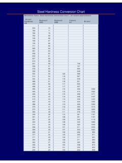
9 GYZJ-934-1 reading: 35 42 56 60 62 75 80 85. Approximate conversion Curves for GYZJ-934-1. 140. s ker 130. Vic nell Rockwell "B" (1/16" ball 100 kg load). 120 Rockwell "E" (1/8" ball 100 kg load). Brin "H". Rockwell "F" (1/16" ball 60 kg load) Rockwell Brinnell (10 mm ball 500 kg load). 110 Vickers Pyramid Numbers Rockwell-Brinell-Vickers Numbers " ". 100 ll "E ll "F. kwe Rockwe Roc 90. B". ll ". we ck 80. Ro 70. 60. 50. 40. 30. 20 Webster 10. 0. 35 40 50 60 70 80 90 100. Barber-Colman Impressor Number Approximate conversion Curves for GYZJ-935 & GYZJ-936. 90. 80 6. 93. J- 70 YZ. G. Type D Durameter 60. 50. 40. 5. -93. ZJ. GY. 30. 20. 10. 0. 50 60 70 80 90. Impressor Dial Indication 1260-IN-010-0-04 Barber-Colman Company, Loves Park, IL Page 5 of 8. The Impressor Operating Information (continued). Approximate conversion chart for GYZJ-934-1 Appoximate conversion chart for Brinnel Vickers Webster Rockwell GYZJ-935 and GYZJ-936.
10 GYZJ-934-1. 10mm 500kg 5kg Model B B E F H Type D. GYZJ-935 GYZJ-936. 35 21 32 Durometer 36 22 35 52 6. 37 23 37 53 9. 38 24 40 54 12. 39 25 42 55 15. 40 25 26 45 56 18. 41 25 27 47 57 21. 42 26 28 49 58 24. 43 27 29 51 59 27. 44 27 30 54 60 30. 45 28 30 56 61 32. 46 29 31 58 62 35. 47 30 32 23 60 63 38. 48 30 33 26 62 64 40. 49 31 34 28 64 65 43. 50 32 35 31 66 66 45. 51 33 36 34 68 67 48. 52 34 38 36 70 68 22 50. 53 35 39 39 30 72 69 26 52. 54 37 40 41 34 73 70 30 54. 55 38 41 44 37 75 71 34 57. 56 39 43 46 40 77 72 38 59. 57 40 44 48 43 78 73 41 61. 58 42 45 50 46 80 74 45 63. 59 43 47 53 48 82 75 48 65. 60 45 49 55 51 83 76 51 67. 61 46 50 57 54 85 77 54 69. 62 48 52 59 56 86 78 57 70. 63 50 54 61 59 88 79 60 72. 64 51 56 63 61 89 80 63 74. 65 53 58 65 63 90 81 66 76. 66 55 60 67 66 92 82 69 77. 67 57 62 69 68 93 83 71 79.