Transcription of THE MclNTOSH MR 77 SOLID STATE FM/FM STEREO …
1 THE MclNTOSH MR 77 SOLID STATE FM/FM STEREO TUNER. Reading Time: 24 Minutes Price $ Your MR 77 FM/FM STEREO Tuner will give you many years of pleasant and satisfactory performance. If you have any questions, please contact: CONTENTS. CUSTOMER SERVICE. MclNTOSH Laboratory Inc. SERVICE CONTRACT .. 1. 2 Chambers Street Binghamton, New York 13903 INSTALLATION .. 2, 3. Phone: 607-723-3512. HOW TO . 4. WARNING: TO PREVENT FIRE OR BACK PANEL INFORMATION .. 5, 6. SHOCK HAZARD, DO NOT EXPOSE. THIS UNIT TO RAIN OR MOISTURE. FRONT PANEL INFORMATION .. 6, 7. LISTENING TO THE MR 77 .. 7. TECHNICAL DESCRIPTION .. 8, 9. Take Advantage of 3 years PERFORMANCE LIMITS AND RATINGS .. 9. of FREE Service .. PERFORMANCE CHARTS .. 10, 11. Fill in the Application NOW. BLOCK DIAGRAM .. 12. THREE YEAR SERVICE CONTRACT. An application for a FREE THREE YEAR SERVICE CONTRACT is included with this manual. The terms of the contract are: or mishandling is not covered by the SER- VICE CONTRACT.
2 4. The SERVICE CONTRACT is issued to you as the original purchaser. To protect you from 1. MclNTOSH will provide all parts, materials and misrepresentation this contract cannot be labor needed to return the measured perform- transferred to a second owner. ance of the instrument to the original per- formance limits free of any charge. The 5. For your protection MclNTOSH selects only SERVICE CONTRACT does not cover any ship- dealers who have technical competence to ping costs to and from the authorized service guide purchasers fairly, and provide service agency or the factory. when necessary. To receive the SERVICE. CONTRACT your purchase must be made 2. Any MclNTOSH authorized service agency will from a MclNTOSH franchised dealer. repair all MclNTOSH instruments at normal service rates. To receive the free service un- 6. Your completely filled in application for a der the terms of the SERVICE CONTRACT, the SERVICE CONTRACT must be postmarked SERVICE CONTRACT CERTIFICATE must ac- within 30 days of the date of purchase of company the instrument when taken to the the instrument.
3 Service agency. 7. To receive the SERVICE CONTRACT all in- 3. Always have service done by a MclNTOSH formation on the application must be filled authorized service agency. If the instrument in. The SERVICE CONTRACT will be issued is modified or damaged as a result of un- when the completely filled in application authorized repair the SERVICE CONTRACT is received at MclNTOSH Laboratory Incor- will be cancelled. Damage by improper use porated in Binghamton, New York. 1. Copyright 1970 By MclNTOSH Laboratory Inc. Installation Adequate ventilation extends the trouble-free life of electronic instruments. It is generally found that each 10 centigrade (18 F) rise in temperature reduces the life of electrical insulation by one half. Adequate venti- lation is an inexpensive and effective means of prevent- ing insulation breakdown that results from unneces- sarily high operating temperatures. The direct benefit of adequate ventilation is longer, trouble-free life.
4 Allow at least 15 inches deep x 17 inches wide x 6. inches high for mounting the MR 77. Always allow for air flow by either ventilation holes or space next to the bottom of the tuner and a means for warm air to If the cutout is to be located from the front of the panel, escape at the top. begin at step 2. If the cutout is to be located from the It is recommended that the MR 77 be mounted in a rear of the panel, begin here. normal or horizontal position. However, with adequate ventilation the tuner can be mounted in any position. 1. On the back of the cabinet panel, scribe a vertical centerline through the exact center of the area in To prepare the MR 77 for installation remove the which the cutout is to be made. plastic protective covering. Turn the MR 77 upside down so that it rests on its top on the shipping pallet. Remove Place the template against the back of the panel and the four plastic feet fastened to the bottom of the match the template centerline with the centerline on chassis.
5 The cabinet panel. Next, place the mounting brackets, the parts bag Make sure that there is at least inch clearance be- and the mounting template at hand. tween the bottom of the dashed line of the cutout area on the template and any shelf or brace below The PANLOC professional mounting design elimi- the proposed cutout. nates the need for any shelf or bracket to support the MR 77. It is completely supported by its own mounting Mark the two locating holes ("C" holes on the brackets. mounting template). The design of the mounting template allows you to Drill the two locating holes. Be certain the drill is position or locate the cutout from the front or rear of perpendicular to the panel. the panel to which the instrument is to be mounted. Now position the template on the front of the panel Position the plastic mounting template over the area of by aligning the "C" locating holes on the template the panel to be cut out for installation.
6 With the drill holes. 2. 2. If the cutout is to be located from the front of the panel: With the template in place against the cabinet, mark the "A" and "B" drill holes and the four small holes that identify the corners of the cutout. Join the cor- ner marks with a pencil. The edge of the template can be used as a straight edge. IMPORTANT: DRILL THE 6 HOLES BEFORE MAKING. THE CUTOUT. Accurately drill the three holes on each side of the cutout area with a 3/16 inch drill. With the saw on the INSIDE OF THE PENCIL LINES. carefully cut out the rectangular opening. adjust position latches. Press the latches in and con- Secure the mounting strips to the rear of the cabinet tinue to slide the instrument in until the front panel is panel using two screws from the hardware package. against the cabinet panel. At the bottom front corners of the PANLOC instruments are the PANLOC buttons. Depressing the PANLOC buttons will lock the instru- ment firmly in the installation.
7 Depressing the PANLOC. buttons a second time will release the instrument. You can then slide the instrument forward to the inspection- adjustment position latches will allow the instrument to be slid completely out of the installation. Insert the screws in the center holes of the cabinet panel ("B" holes on the template) and tighten. The screw head should pull into the wood slightly. (Use two inch long screws for panels under inch, or two 1 . inch long screws for panels inch thick and larger.). Attach the mounting brackets to the cabinet panel using four screws. Place the template over the mounting screws. The mounting screws should be centered in the "A" and "B" holes on the template. The sides of the mounting brackets should match the vertical dash lines on the template. If necessary, loosen the screws and push the brackets into alignment and retighten. Insert the power cord through the opening. Carefully slide the MR 77 into the opening so the rails on the bot- tom of the equipment slide in the track of the mounting brackets.
8 Slide the instrument in until it stops at the 3. How to Connect AUDIO OUTPUTS An outdoor antenna is recommended for optimum performance in all areas. In fringe (outlying) areas, best Use the FIXED OUTPUT jacks to connect to a con- results will be obtained with a highly directional FM. ventional control preamplifier which has its own volume antenna used in conjunction with a rotator. Rotate the control. The VOLUME CONTROL does not affect the antenna until the best reception is obtained. Connect output of the tuner at the FIXED OUTPUT jacks. the 300 ohm antenna to the 300W ANT (red) terminals. The output impedance at the FIXED OUTPUTS is 600 ohms. Longer cables than are normally supplied CONNECTING A 75 OHM ANTENNA. can be used to interconnect the MR 77 with other equip- An unbalanced 75 ohm antenna can be connected ment. The length of the cable is limited by the capacity to the MR 77. A "type F" connector is used to connect of the cable.
9 The total capacity must not exceed 1600 the 75 ohm coaxial cable to the back panel 75W ANT. pF. For instance: cables with a capacity of 32 pF per input. foot may be 50 feet long; 16 pF per foot cable may be 100 feet long. A VHF-TV antenna is often effective but the an- tenna must be designed for both FM and TV reception. Connect the leads from the VHF-TV antenna to the Use the FRONT PANEL CONTROLLED jacks to con- 300 ohm ANT (red) terminals. nect to a conventional control preamplifier when use of the tuner volume control is desired. These jacks may CONNECTING AN INDOOR DIPOLE ANTENNA. be used to connect to external equipment such as power amplifiers or tape recorders where control of volume at The flexible folded dipole antenna (300 ohm) is for the tuner is necessary. The load impedance connected use in urban or high strength signal areas. to the front panel controlled packs should not be less Connect the two leads from the dipole to the 300W.
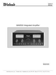
10 Than 47,000 ohms. There is no difference in the signal ANT (red) terminals. The flexibility of the thin flat wire quality or maximum output levels available at each pair assembly permits it to be placed under a rug, tacked of output jacks. behind the STEREO .. or, placed in any other conven- ient location. In some cases, it may be necessary to CONNECTING AN FM ANTENNA "position" the antenna for best signal reception. This should be done before it is permanently located. Avoid One of three antenna systems can be used: (1) an locating this antenna next to other wires or metal ob- outdoor FM antenna, (2) a VHF-TV antenna, or (3) the jects. This antenna may not prove effective in houses indoor dipole supplied with the MR 77. having metal siding or metal-clad insulation. 4. FM ANTENNA. OPTIONAL. 75W. ANTENNA. LEAD-IN. POWER AMPLIFIER. PREAMPLIFIER. LEFT SPEAKER RIGHT S P E A K E R. Back Panel Information TP1 and TP2 does not protect additional equipment connected to Test point TP1 and TP2 is used with the MclNTOSH the back panel AC outlet.