Transcription of THE MIRAGE D1010N-ATV AMPLIFIER ON ATV - Ham TV
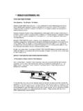
1 P. C. Electronics 2522 Paxson Lane Arcadia CA 91007-8537 USA 2009. Tel: (626) 447-4565 m-th 8am-5:30pm pst (UTC - 8) Tom (W6 ORG) & Mary Ann (WB6 YSS). Web site: Email: ATVinfo @ THE MIRAGE D1010N-ATV AMPLIFIER ON ATV. The MIRAGE D1010N-ATV all-mode 70cm AMPLIFIER now available from MFJ has been specially designed to not only work with CW, SSB and FM but also ATV. Despite all mode claims by other manufacturers, few have the proper additional capacitors required for low power supply and bias supply impedance at all video frequencies up to 5 MHz. Without wideband video amplitude modulation in mind when the amp is designed and tested, the result can be color shift, distorted sync and low color and sound subcarrier output. The D1010N-ATV input power and linear gain curve properly matches the Electronics KPA5, TC70-1 & TXA5-RC ATV. transmitters for over 50 Watts or the 10 Watt TC70-10 or TXA5-70/PA5 modules for full output with applied.
2 The 20 watt TC70-20S or TXA5-70S/PA5-20 first must have the exciter RF pot set mid way before set up so as not to exceed the 15 watt maxi mum peak power input that could blow the first amp stage. The set up procedure must be done to set the sync tip power and then the blanking power to maintain the proper video to sync The sync stretcher circuit in the transmitter modulator found in all Electronics ATV. transmitters compensates for the last 3 dB of output change nonlinearity (gain compression) found in most amateur linear amplifiers. The amp FM/SSB switch only affects automatic T/R dropout time, not amp linearity - SSB is the normal setting for ATV. You must do the setup procedure one time before operation to match your particular transmitter, amp and power supply. Once the blanking pedestal has been set in the transmitter modulator, the proper video to sync ratio will be automatically maintained regardless of camera scene or video gain changes.
3 You need only do the setup again if the applied voltage is changed by more than .5 Volts such as going from a base station power supply set to the nominal Vdc to a mobile or portable application where the battery may drop to Vdc. Readjustment may also be necessary when changing frequency. The sound subcarrier injection may have to be reset (decreased). Do not drive the d1010n with more than 15 Watts input in any mode or you may damage the amps first transistor. Remember that the sync stretcher will still pull the sync up over 15 Watts output even if you can reset the blanking pedestal low enough without video applied. Excessive drive from any video modulated source will result in a distorted picture. ATV is an AM mode which must have the video waveform preserved by driving each AMPLIFIER within its linear range. Normal all mode duty cycle for the d1010n is 5 minutes on and 5 minutes off.
4 For ATV it is 10 minutes on since the normal average power is about half the peak power. However this will vary depending on the heat dissipation. Therefore it is best placed where free air can come in from the sides and rise up from the heatsink fins. A fan (Radio Shack has both 12 Vdc and 120 Vac) blowing across the fins will help lengthen the duty cycle a little and life time. MIRAGE makes a continuous duty version with a much larger heat sink for repeaters. If at any time the thermal relays shut down the amp while in operation, this says that your duty cycle is too long and cooling insufficient. While this protects the amp initially, any repetition can only stress and weaken the parts and PC board in the amp. The 50 coax between the driver and amp as well as to the antenna must be of good quality and at least 95% shielding. Belden 8214.
5 Or 9913 are suggested. Take no shortcuts when putting together the coax and connectors as small bumps in the coax line can cause a VSWR (10% max reflected) at UHF and possible stray RF getting into your camera or mic. See the ARRL Handbook for proper connector assembly. Do not use any right angle connectors, and minimize any adapters or extensions to keep losses down. 2002 d1010n PC EL. SET UP: 1. Connect to its own regulated supply capable of 20 Amps. Keep leads short and direct to the power supply terminals. 2. Connect a thruline RF power meter capable of reading up to 100 Watts on 70cm at the amp output. 3. With no video connected to the transmitter, turn the exciter RF. out pot to mid way and the Pedestal pot to full CCW. Set the RF. drive pot for 90 Watts - this is your peak envelope power on the sync tip. Next, turn the blanking pedestal pot to 50 Watts.
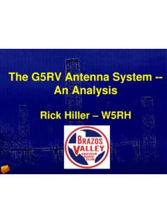
6 4. Remove the power meter from the antenna line as it has no further relevance under video modulation. Except for special RF watt meters used by broadcast TV, most RF wattmeters do not read Fan 50 Ohm accurate average power with AM modulations above 50 kHz. Camera TC70 D1010 Antenna RF Wattmeter Your peak (sync) power will be constant at the 90 Watts you set during video modulation due to the sync stretcher, but the System Block Diagram with RF wattmeter for intial setup. wattmeter will read about half that or less with whiter scenes. Antenna must be a resonant 50 broadband 70cm type such as the 5. Connect up your camera or other video source and have a distant DS FO25-ATV, OAL 5l-70cm, etc. station talk in your video gain level to the point just before white clipping or smearing - don't over modulate and splatter. If excessive crosshatch is noted with color video, turn down the sound subcarrier injection level.
7 P. C. Electronics 2522 Paxson Lane Arcadia CA 91007-8537 USA 2009. Tel: (626) 447-4565 m-th 8am-5:30pm pst (UTC - 8) Tom (W6 ORG) & Mary Ann (WB6 YSS). Web site: Email: ATVinfo @ MIRAGE AMPLIFIER ATV modifications Revisited The MIRAGE D1010-ATV, D100-ATV, D3010-ATV or respective repeater versions all have the modification done at the factory for ATV and all mode amateur radio service. The non-ATV version has a feedback network between the base and collector to prevent low frequency oscillation in the final AMPLIFIER transistors. This network, however, will also distort the color, sound and horizontal sync in ATV operation. The modification engineered by P. C. Electronics for MIRAGE in the mid 1980's, simply removes this feedback network consisting of a series .1 mF disc, 10 Ohm resistor and wire wound inductor. However, depending on the age of the AMPLIFIER , you need to check to make sure that there is a 50 Ohm 10 Watt power resistor connected between the RF output and ground.
8 This will give a 50 Ohm low frequency termination but, being wire wound, look like a high value inductor or RFC at 70cm. The resistor will prevent low frequency oscillation when the series feed back networks across the base to collector of the finals are removed. If there is no 50 Ohm 10 watt wire wound power resistor located on the output side of a 200 pF uncased mica cap,, you can get one from Radio Shack (271-133) and solder it in. The original modifications appeared in the ATV Q and A column by W6 ORG in the first quarter of 1989 issue of Amateur Television Quarterly. Amplifiers manufactured after this date have the power resistor and other modifications so all that is needed to make a standard amp into the ATV version is to remove the series feedback network. Those manufactured before that date need to be visually checked for some added 470 mF, 100 mF 50V aluminum electrolytic caps and.
9 125V ceramic disc caps. Refer to the schematic. There should be all 3 of these caps in parallel on the + V line just after the fuse. There are should be 100 mF in parallel with .1 mF disc caps to ground between the RF chokes that feed the bias to the driver and finals and also the collectors. All these capacitors are necessary to keep the bias and collector supply voltages stable and constant during the high peak currant swings at the video modulation rates up to 5 MHz. The 1 pF disc caps at both RF. connectors reduced some of the loss by matching our some of the internal coax lead inductance by better than 1. dB. This will help in both transmit and receive. Make the cap leads direct and short at the connectors. The modifications have no effect on other modes, except maybe to inprove the SSB audio envelope linearity. The mode switch should be left in the SSB position for ATV so that the automatic RF T/R sensinng does not drop out or chatter in the case of a very white picture where average power will be low - you may want to increase the delay.
10 This switch has nothing to do with the AMPLIFIER bias or linearity. If used at a repeater, you may also want to remove the power leads and replace with a SO-239 connector and bypass with 100 pF caps. Yes, it is absolutely necessary to first make sure that the peak envelope power from your ATV transmitter does not exceed the maximum input power specified for your specific amp before connecting up and follow the set up proceedure on the first page exactly - do not blind tweek or vary the RF drive, blanking pedestal or video gain controls by just watching the picture. You must do the set up procedure as described with a RF power meter - borrow one if you have to - in order to have a stable picture with the proper video to sync ratio and not splatter the band. D1010 vs D100. The only difference between these two models is a resistive Pi network attenuator on the input.